
An Accurate Design Method of Shrinkage Dimensions of Castings Based on Local Envelope Density

A design method, casting shrinkage technology, applied in constraint-based CAD, design optimization/simulation, geometric CAD, etc., can solve the problems of large dimensional accuracy errors and insignificant accuracy effects of castings, and achieve the solution of large accuracy errors and design methods Reasonable, feasible and operable

Active Publication Date: 2021-11-09
HARBIN INST OF TECH
View PDF0 Cites 0 Cited by
  • Summary
  • Abstract
  • Description
  • Claims
  • Application Information

AI Technical Summary

Problems solved by technology

[0004] The purpose of the present invention is to solve the problem that the existing empirical scaling method has large casting dimensional accuracy errors, and the effect of the overall envelope density method on improving the casting dimensional accuracy is not obvious, and to provide a casting shrinkage size based on local envelope density. precise design method

Method used

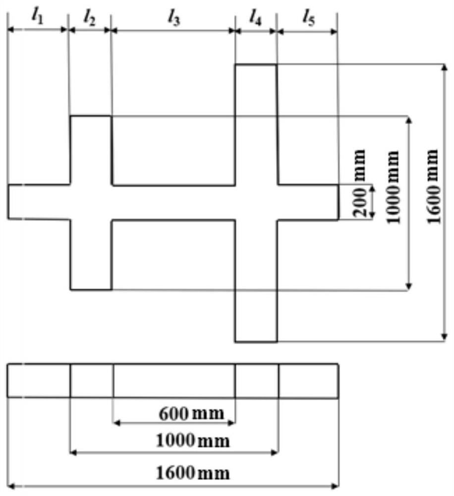

Image

  • An Accurate Design Method of Shrinkage Dimensions of Castings Based on Local Envelope Density
  • An Accurate Design Method of Shrinkage Dimensions of Castings Based on Local Envelope Density
  • An Accurate Design Method of Shrinkage Dimensions of Castings Based on Local Envelope Density

Examples


specific Embodiment approach 1

[0020] Specific Embodiment 1: In this embodiment, an accurate design method of casting shrinkage size based on local envelope density is completed according to the following steps:

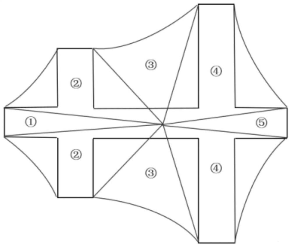
[0021] 1. Divide the test model into several local envelopes according to the contraction center ray division method, first calculate the local envelope density of any local envelope, and according to the quadratic relationship curve between the local envelope density and the shrinkage rate, get Calculate the shrinkage of the local envelope, and then use the same method to obtain the shrinkage of all the local envelopes of the test model;

[0022] 2. Convert the shrinkage rate of all local envelopes of the test model into the shrinkage rate of the same part on the casting. The conversion formula is as follows:

[0023] ε li = α 1 ·ε 1 +α 2 ·ε 2 +…+α n ·ε n +(1-α 1 -α 2 -...-α n )·ε 0

[0024] In the formula, ε n Represents the shrinkage rate of the nth local envelope of the test model...

specific Embodiment approach 2

[0028] Specific embodiment two: the difference between this embodiment and specific embodiment one is: the shrinkage center ray division method described in step one includes the following steps: first determine the shrinkage center of the test model and the envelope of the test model, and then from the shrinkage Make several rays from the center to the envelope of the test model, and the closed space formed by two adjacent rays and the edge of the envelope is a local envelope.

[0029] Other steps are the same as in the first embodiment.

specific Embodiment approach 3

[0030] Embodiment 3: The difference between this embodiment and Embodiment 1 or 2 is that the contraction center of the test model is the center of mass of the test model.

[0031] Other steps are the same as those in Embodiment 1 or 2.


PUM


Abstract

The invention relates to an accurate design method of casting shrinkage size based on local envelope density, which relates to the technical field of casting size precision design. The purpose of the present invention is to solve the problems that the existing empirical scaling method has large casting dimensional accuracy errors, and the overall envelope density method has no obvious effect on improving the casting dimensional accuracy. Method: Divide the test model into several local envelopes according to the shrinkage center ray division method, first calculate the local envelope density of any local envelope, and according to the quadratic relationship curve between the local envelope density and the shrinkage rate, get Calculate the shrinkage rate of the local enveloping body, and then use the same method to obtain the shrinkage rate of all the local enveloping bodies of the test model, and then convert the shrinkage rate of all the local enveloping bodies of the test model into the shrinkage rate of the same part of the casting . The invention can obtain an accurate design method of casting shrinkage size based on local envelope density.

Description

technical field [0001] The invention relates to the technical field of dimension precision design of castings, in particular to an accurate design method of shrinkage dimensions of castings based on local envelope density. Background technique [0002] In order to achieve the purpose of reducing the production cost and machining times of parts, when factories and enterprises are constantly looking for various methods, the emergence of near net shape technology undoubtedly provides a powerful means for this, so casting methods are also emerging in an endless stream, so as to achieve high quality and low cost. Cost-effective part forming, and its research mainly focuses on two aspects of shape control and controllability, so the precision control of shrinkage size of castings has become an indispensable part of the field of near-net shape precision shape control. Since castings are mechanically hindered by structures such as molds and cores during shrinkage, castings with diff...

Claims


Application Information

Patent Timeline
Patent Type & Authority Patents(China)
IPC IPC(8): G06F30/17G06F30/23G06F111/04
CPCG06F30/17G06F30/23G06F2111/04
Inventor 黄西西吴士平薛祥戴贵鑫王明杰陈润瑞彭恒元
Owner HARBIN INST OF TECH
Learn More