
Surface reflectance correction method and device based on remote sensing image

A technology of surface reflectivity and remote sensing images, applied in the computer field, can solve problems such as difficult to accurately reflect the surface reflection of the target area, and achieve the effect of a simple method

Inactive Publication Date: 2021-06-22
CHINA AGRI UNIV
View PDF5 Cites 3 Cited by
  • Summary
  • Abstract
  • Description
  • Claims
  • Application Information

AI Technical Summary

Problems solved by technology

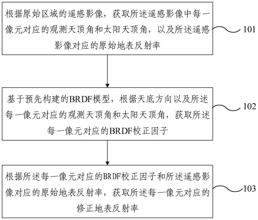
[0005] The present invention provides a ground surface reflectance correction method and device based on remote sensing images, which is used to solve the defect in the prior art that it is difficult to accurately reflect the reflection of the ground surface of the target area directly based on the remote sensing image acquisition of the ground reflectance of the target area. Improve the surface reflectance of the target area based on remote sensing images to more accurately reflect the surface reflection of the target area

Method used


Image

  • Surface reflectance correction method and device based on remote sensing image
  • Surface reflectance correction method and device based on remote sensing image
  • Surface reflectance correction method and device based on remote sensing image

Examples


Embodiment Construction

[0038] In order to make the purpose, technical solutions and advantages of the present invention clearer, the technical solutions in the present invention will be clearly and completely described below in conjunction with the accompanying drawings in the present invention. Obviously, the described embodiments are part of the embodiments of the present invention , but not all examples. Based on the embodiments of the present invention, all other embodiments obtained by persons of ordinary skill in the art without creative efforts fall within the protection scope of the present invention.

[0039] In the description of the present invention, it should be noted that unless otherwise specified and limited, the terms "installation", "connection" and "connection" should be understood in a broad sense, for example, it can be a fixed connection or a detachable connection. Connected, or integrally connected; it can be mechanically connected or electrically connected; it can be directly...


PUM


Abstract

The invention provides a surface reflectance correction method and device based on a remote sensing image. The method comprises the steps of: according to the remote sensing image of an original region,obtaining an observation zenith angle and a solar zenith angle corresponding to each pixel in the remote sensing image and obtaining original surface reflectance corresponding to the remote sensing image; based on a pre-constructed BRDF model, obtaining a BRDF correction factor corresponding to each pixel according to the nadir direction and the observation zenith angle and the solar zenith angle corresponding to each pixel; and obtaining corrected surface reflectance corresponding to each pixel according to the BRDF correction factor corresponding to each pixel and the original surface reflectance corresponding to the remote sensing image. According to the surface reflectance correction method and device based on the remote sensing image, the corrected surface reflectance corresponding to each pixel can more accurately reflect the reflection condition of the surface of the target area, and the method for obtaining the corrected surface reflectance corresponding to each pixel is simple and efficient.

Description

technical field [0001] The invention relates to the field of computer technology, in particular to a method and device for correcting ground reflectance based on remote sensing images. Background technique [0002] BRDF (Bidirectional Reflectance Distribution Function, bidirectional reflection distribution function), can describe the distribution of incident light in each outgoing direction after being reflected by a certain surface. [0003] BRDF models can be divided into three categories: empirical statistical BRDF models, physical BRDF models, and semi-empirical kernel-driven BRDF models. Among them, the semi-empirical kernel-driven BRDF model is widely used for its simplicity and efficiency. By inputting the relevant information of any observed zenith angle of the target area containing the same ground object into the constructed semi-empirical kernel-driven BRDF model, the surface reflectance of the observed zenith angle in the target area can be obtained without going...

Claims


Application Information

Patent Timeline
IPC IPC(8): G01N21/47
CPCG01N21/4738
Inventor 苏伟谢茈萱王新盛张颖陶万成
Owner CHINA AGRI UNIV
Learn More