


Quick Research
Generate reliable direction feasibility study reports for your R&D in just a few steps.

Technical Q&A
Discover and master advanced knowledge NOW. Basics, ideas, possibilities, all at once.

Find Solutions
As an expert in R&D theories, this can generate solutions to your technical problems instantly.

Evaluate Feasibility
Analyze your overall solution with one click, know your potential R&D risks in advance.

Monitor Landscape
Get weekly tech updates, stay abreast of the latest tech innovations and key insights.
Wave energy glider hydrodynamic fin testing device
A testing device and wave energy technology are applied in the field of hydrodynamic vane testing devices for wave energy gliders, which can solve the problems of large changes in sea conditions, high recovery costs, and high sea trial costs, so as to improve the efficiency of using wave energy and improve the overall quality of life. The effect of improving the power situation and improving the efficiency analysis
- Summary
- Abstract
- Description
- Claims
- Application Information
AI Technical Summary
Problems solved by technology
Method used
Image

Examples
Embodiment 1
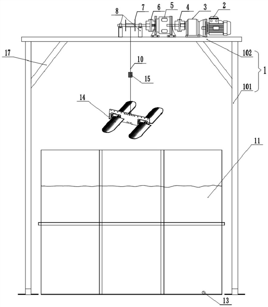
[0037] The embodiment is basically as attached figure 1 Shown: a hydrodynamic fin testing device for a wave energy glider, comprising a stand 1 and a large water tank 11, the top of the stand 1 is rotatably connected with a reel 7, and the stand 1 in this embodiment includes an equipment platform 102 and Two support columns 101, and the equipment platform 102 is located between the two support columns 101. In this embodiment, a reinforcing rib 17 is fixedly connected between the equipment platform 102 and the two supporting columns 101 by screws, and the setting of the reinforcing rib 17 can strengthen Stability between the equipment platform 102 and the support column 101 , the equipment platform 102 and the two support columns 101 make the platform 1 a door-shaped frame structure as a whole, and the water tank 11 is located below the equipment platform 102 .
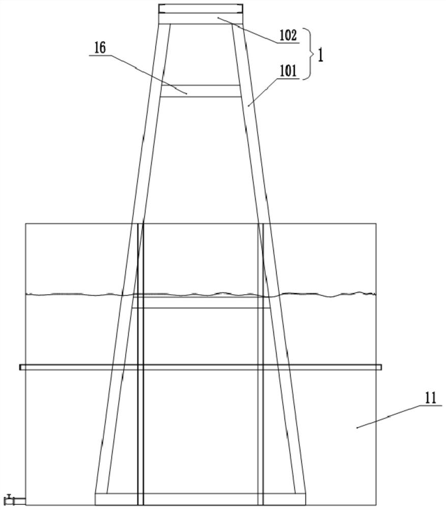
[0038] combine figure 2 As shown, the support columns 101 in this embodiment are all A-shaped structures, which ca...
Embodiment 2
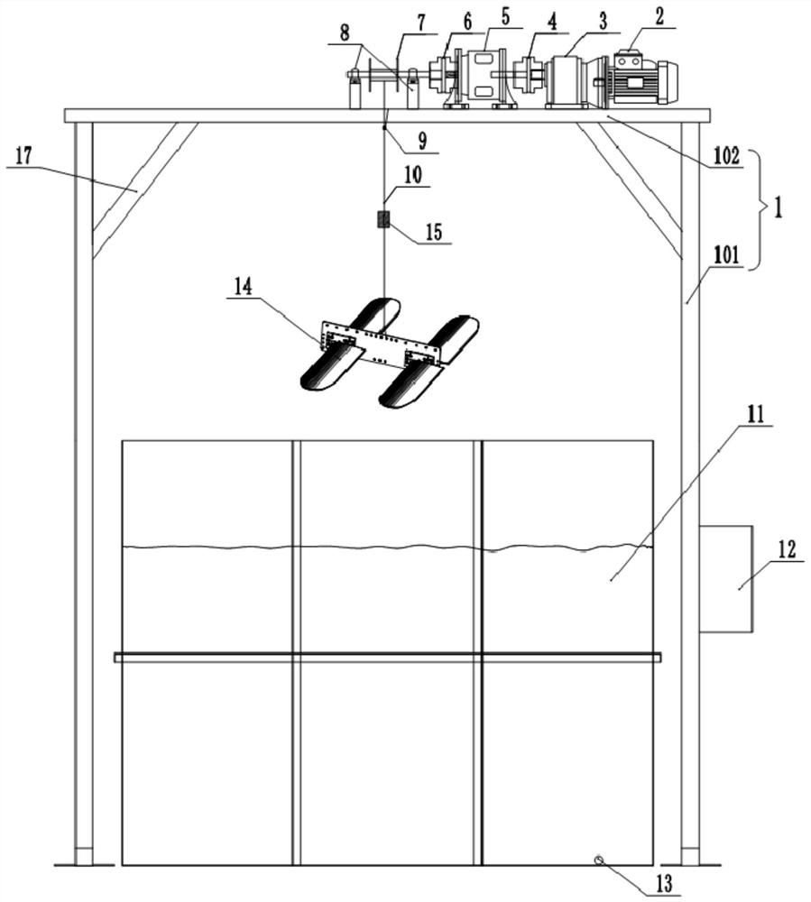
[0050] like image 3 As shown, a wave energy glider hydrodynamic fin testing device differs from Embodiment 1 in that: a limit sensor 9 is installed below the equipment platform 102, and the limit switch in this embodiment adopts a proximity switch in the prior art . An electric control box 12 is installed on the stand 1, and in this embodiment, the electric control box 12 is installed on the lower part of one of the two support columns 101 by screws.
[0051] Limit sensor 9, clutch 5 and motor 2 are all electrically connected with electric control box 12, and controller etc. are installed in electric control box 12, limit sensor 9 can transmit signal to The electric control box 12 enables the electric control box 12 to control the clutch 5 to disengage.
[0052] In actual use, when the reel 7 rotates to make the rope 10 drive the underwater propeller 14 to lift upward, when the underwater propeller 14 is lifted to the water surface away from the water tank 11, when the limi...
PUM
 Abstract
Description
Claims
Application Information
 - R&D Engineer
- R&D Manager
- IP Professional
- Industry Leading Data Capabilities
- Powerful AI technology
- Patent DNA Extraction
Browse by: Latest US Patents, China's latest patents, Technical Efficacy Thesaurus, Application Domain, Technology Topic, Popular Technical Reports.
© 2024 PatSnap. All rights reserved.Legal|Privacy policy|Modern Slavery Act Transparency Statement|Sitemap|About US| Contact US: help@patsnap.com