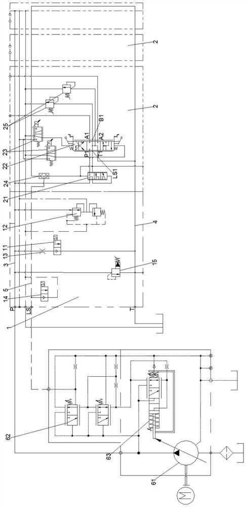
Load-sensitive multi-way valve, boom hydraulic control system and concrete pump truck

A load-sensitive, multi-way valve technology, used in fluid pressure actuating system components, fluid pressure actuating devices, servo motors, etc. Guaranteed service life, good flow stability, and energy saving effects

Pending Publication Date: 2021-06-22
CHANGDE ZHONGLIAN ZHONGKE HYDRAULIC
View PDF10 Cites 1 Cited by
  • Summary
  • Abstract
  • Description
  • Claims
  • Application Information

AI Technical Summary

Problems solved by technology

[0004] For example, the boom control valve group includes a pressure compensation valve and a main spool. Under normal working conditions, the hydraulic oil output by the variable pump flows to the main spool through the pressure compensation valve to control the reversing of the main spool to realize the control of the action of the actuator. Control; when the concrete pump truck starts pouring, the boom control valve group is in the neutral standby state for a long time, and the reversing working time is short; when the boom control valve group is in the neutral standby state, the neutral function of the load sensitive multi-way valve is In the closed state, according to the load feedback pressure, the variable pump swings to a small swing angle, only provides the small leakage flow of itself and the boom control valve group, and slowly unloads from the casing of the variable pump. Because the unloading flow is too small, it cannot Take away the heat generated when the variable pump is in neutral position, which will lead to a gradual rise in the oil temperature at the outlet of the variable pump and in the housing, which will affect the service life of the variable pump and is easy to leak
[0005] In this regard, an additional three-way flow valve is usually installed for unloading to prevent the phenomenon of local oil temperature rise at the outlet of the variable pump; The valve overflows, at this time, the flow stability of the working port is poor, and there is excess high-pressure oil loss, resulting in waste of energy

Method used


Image

  • Load-sensitive multi-way valve, boom hydraulic control system and concrete pump truck

Examples


Embodiment Construction

[0040] Specific embodiments of the present invention will be described in detail below in conjunction with the accompanying drawings. It should be understood that the specific embodiments described here are only used to illustrate and explain the present invention, and are not intended to limit the present invention.

[0041] In addition, the terms "first" and "second" are only used for the purpose of description, and cannot be understood as indicating or implying relative importance or implicitly specifying the number of indicated technical features. Therefore, the terms "first", "second" are limited to A "second" feature may explicitly or implicitly include one or more of said features.

[0042] In the description of the present invention, it should be noted that unless otherwise specified and limited, the terms "installation", "setting", and "connection" should be understood in a broad sense, for example, it can be a fixed connection or a detachable connection. A connectio...


PUM


Abstract

The invention relates to a multi-way valve, and discloses a load-sensitive multi-way valve, a boom hydraulic control system and a concrete pump truck. The load-sensitive multi-way valve comprises an oil inlet unit, at least one working unit, a main oil inlet path for communicating an oil inlet of the oil inlet unit with oil inlets of the working units, a main oil return path for communicating with an oil return port of the oil inlet unit and oil return ports of the working units, and a load feedback oil path for communicating with a feedback oil port of the oil inlet unit and feedback oil ports of the working units, wherein the oil inlet unit comprises a flushing mechanism, the flushing mechanism is connected between the main oil inlet path and the main oil return path, and the flow pumped into the oil inlet unit can be unloaded when the system is in a neutral-position standby state. The load-sensitive multi-way valve not only can prevent the temperature of local oil at the outlet of a variable pump and in the shell from being too high, but also is good in flow stability and free of excessive high-pressure oil overflow loss.

Description

technical field [0001] The invention relates to a multi-way valve, in particular to a load sensitive multi-way valve. In addition, it also relates to a boom hydraulic control system with the load sensitive multi-way valve and a concrete pump truck with the boom hydraulic control system. Background technique [0002] The concrete pump truck is a special vehicle that integrates the pumping mechanism and the boom system on the chassis of the car. The boom system of the concrete pump truck is mainly used for conveying and distributing concrete, that is, the expansion and retraction of the boom is controlled by the oil cylinder, and the concrete is delivered to the designated pouring point in conjunction with the rotation of the turntable. During pouring, there are high requirements on the stability and position accuracy of the boom mechanism. Therefore, the small flow stability of the boom hydraulic control valve group is required, and the response time is fast. [0003] At pr...

Claims


Application Information

Patent Timeline
IPC IPC(8): F15B11/032F15B11/08F15B13/04F15B21/0423F15B21/08
CPCF15B11/032F15B11/08F15B13/0401F15B21/0423F15B21/087
Inventor 杨朋
Owner CHANGDE ZHONGLIAN ZHONGKE HYDRAULIC
Why Eureka
Try Eureka