
Emergency braking device for elevator multi-parameter detection based on embedded technology

An emergency braking and multi-parameter technology, which is applied to elevators, transportation and packaging, elevators, etc. in buildings, can solve problems such as high consumption and threats to passengers' personal safety, and achieve the effect of protecting passengers' safety

Active Publication Date: 2021-06-22
福建省特种设备检验研究院泉州分院 +2
View PDF6 Cites 0 Cited by
  • Summary
  • Abstract
  • Description
  • Claims
  • Application Information

AI Technical Summary

Problems solved by technology

[0003] The current elevators can be divided into low-speed elevators (less than 4 meters per second), fast elevators (4 to 12 meters per second) and high-speed elevators (above 12 meters per second) according to the speed. However, in the actual operation process, the operating speed of the elevator They are all fixed, that is, low-speed elevators (below 4 meters per second), fast elevators (4 to 12 meters per second) and high-speed elevators (above 12 meters per second), and the number of passengers they carry will also affect the running speed of the elevator. In the process of operation, it will also consume too much because the output under no-load and load conditions is the same; in addition, when the traditional elevator is in use, it will also pose a threat to the personal safety of passengers due to the wear and tear of the cable. Therefore, in this example Aim to design an emergency braking device based on embedded technology for multi-parameter detection of elevators

Method used


Image

  • Emergency braking device for elevator multi-parameter detection based on embedded technology
  • Emergency braking device for elevator multi-parameter detection based on embedded technology
  • Emergency braking device for elevator multi-parameter detection based on embedded technology

Examples


Embodiment Construction

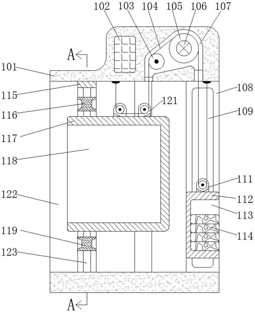
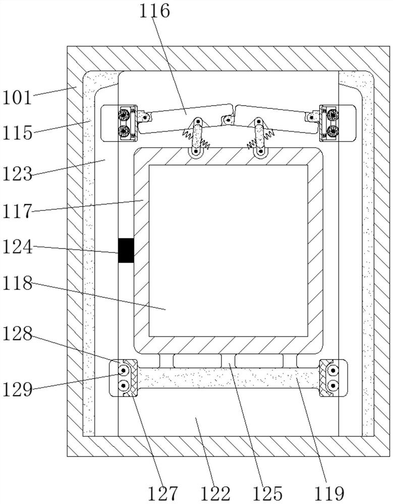
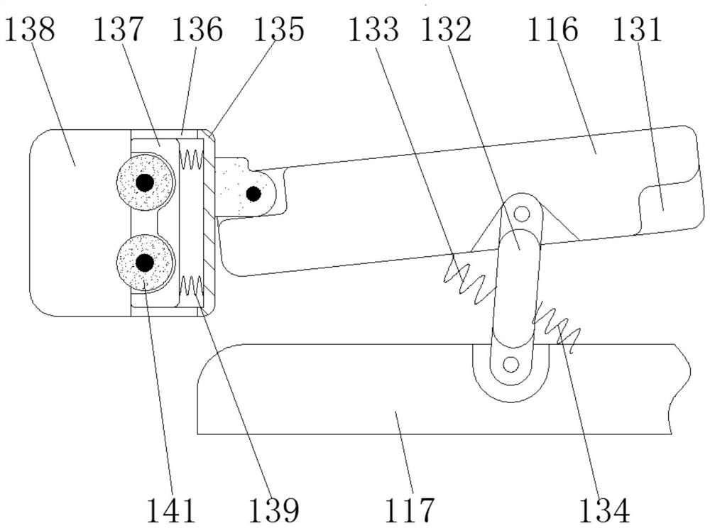
[0026] Combine below Figure 1 to Figure 7 The present invention is described in detail, and for convenience of description, the orientations mentioned below are now stipulated as follows: figure 1 The up, down, left, right, front and back directions of the projection relationship itself are the same.

[0027] The present invention relates to an emergency braking device based on embedded technology for multi-parameter detection of elevators. The present invention will be further described below in conjunction with the accompanying drawings of the present invention:

[0028] An emergency braking device based on embedded technology multi-parameter detection of the elevator described in the present invention, as attached figure 1 - attached Figure 7 The shown emergency braking device for multi-parameter detection of the elevator includes a frame 101 arranged inside the building wall, and the frame 101 is provided with an elevator shaft 122 penetrating left and right, and the l...


PUM


Abstract

The invention discloses an emergency braking device for elevator multi-parameter detection based on an embedded technology. The emergency braking device comprises a frame, wherein an elevator shaft penetrating left and right is arranged in the frame, a driving chamber is arranged in the inner wall of the upper side of the elevator shaft, a driving wheel is rotatably arranged in the driving chamber, the driving wheel is driven by a driving motor fixedly arranged in the inner wall of the rear side of the driving chamber, a guide wheel is rotatably arranged on the left side of the driving motor and located in the driving chamber, counter-weight steel frames are symmetrically and fixedly arranged on the inner walls of the front side and the rear side, close to a right end opening, of the elevator shaft correspondingly, and the upper end and the lower end of the counterweight steel frame are fixedly connected with the inner walls of the upper side and the lower side of the elevator shaft correspondingly. The embodiment of the invention aims to design the emergency braking device for elevator multi-parameter detection based on the embedded technology.

Description

technical field [0001] The invention relates to the technical field of vertical elevators, in particular to an emergency braking device for elevator multi-parameter detection based on embedded technology. Background technique [0002] An elevator (elevator, vertical elevator) is a transportation device that transports pedestrians or goods vertically. Elevators serve buildings with specified floors. Vertical elevators have a car that runs between at least two vertical or rigid guide rails with an inclination angle of less than 15°, which is convenient for passengers to enter and exit or to load and unload goods. [0003] The current elevators can be divided into low-speed elevators (less than 4 meters per second), fast elevators (4 to 12 meters per second) and high-speed elevators (above 12 meters per second) according to the speed. However, in the actual operation process, the operating speed of the elevator They are all fixed, that is, low-speed elevators (below 4 meters p...

Claims


Application Information

Patent Timeline
IPC IPC(8): B66B5/00B66B5/12B66B5/18B66B1/06B66B1/34B66B11/08
CPCB66B5/00B66B5/125B66B5/18B66B1/06B66B1/3476B66B11/008Y02B50/00
Inventor 林宁张伟雷利勇王文征刘爱国鲍才瑜
Owner 福建省特种设备检验研究院泉州分院
Learn More