Hollow stabilizer bar conveying system

A conveying system and stabilizer bar technology, which is applied to conveyors, conveyor objects, transportation and packaging, etc., can solve the problems of high labor intensity, large waist injury, low work efficiency, etc., to save manpower and material resources, smooth movement, The effect of improving work efficiency

Inactive Publication Date: 2021-06-22
江苏新悦自动化有限公司
View PDF5 Cites 1 Cited by
  • Summary
  • Abstract
  • Description
  • Claims
  • Application Information

AI Technical Summary

Problems solved by technology

[0002] The hollow stabilizer bar is a conventional component in the field of automobile manufacturing. During the mass production process of the hollow stabilizer bar, it is necessary to place the hollow stabilizer bar on the corresponding equipment for corresponding processing. In order to improve its feeding efficiency and meet the requirements of automation To meet the needs of production development, a feeding rack-type feeding structure is adopted, but the simple feeding rack form also requires personnel to participate in the operation, which belongs to semi-automation. Although it can achieve the effect of feeding, but its feeding and feeding The process is all manually operated, and the operator needs to bend over and lift each one. Long-term operation will cause great damage to the waist, labor intensity is high, time-consuming and labor-intensive, and work efficiency is low. The stabilizer bar is placed at the designated conveying position, which greatly reduces the low work efficiency, and also greatly increases the labor intensity of the operator

Method used


Image

  • Hollow stabilizer bar conveying system
  • Hollow stabilizer bar conveying system
  • Hollow stabilizer bar conveying system

Examples


Embodiment

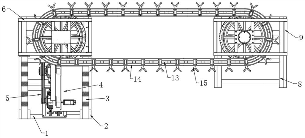
[0039] Please refer to the attached Figure 1-6 , a hollow stabilizer bar delivery system comprising:

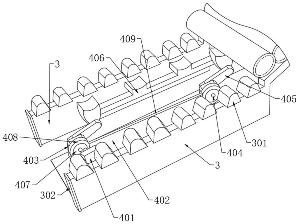
[0040] The first base 1, a pair of first supporting legs 2 are vertically welded on one side of the first base 1, and a pair of first supporting legs 2 are welded with a feeding plate 3, and a pair of feeding plates 3 are rotationally connected with a second A driving device 4 .

[0041]Further, the set first base 1 is in the shape of a rectangular frame, which is stable and saves the use of materials. A layer of rubber pad is provided on the contact surface between the first base 1 and the ground to play the role of anti-slip and anti-friction. Prevent the first base 1 made of metal from being directly contacted with the ground to cause abrasion.

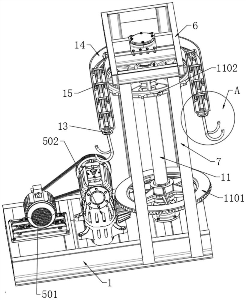
[0042] The second driving device 5 is formed on the upper surface of the first base 1 .

[0043] Further, a connecting plate is horizontally connected to the first base 1, and the second driving device 5 is screwed on the conn...


PUM


Abstract

The invention discloses a hollow stabilizer bar conveying system. The hollow stabilizer bar conveying system comprises a first base, a second driving device, a first top plate, a second base, a driving conveying shaft, a driven conveying shaft and a conveying chain; a pair of first supporting legs are vertically welded to one side of the first base; feeding plates are welded to the pair of first supporting legs; a first driving device is rotationally connected between the pair of feeding plates; a second top plate is arranged on the second base; and third supporting legs are vertically welded between the four corners of the lower surface of the second top plate and the second base. A feeding rod is driven by a pair of swing arms to feed a hollow stabilizer bar; an arc-shaped surface is arranged on the contact surface of the feeding rod and the hollow stabilizer bar; the effect of supporting the hollow stabilizer bar is achieved; the hollow stabilizer bar is supported to the V-shaped hook-shaped position at the lower end of a conveying rod; the problem that manual operation is adopted in the original feeding process is solved; and the working efficiency is improved.

Description

technical field [0001] The invention belongs to the technical field of conveying system equipment, and in particular relates to a hollow stabilizer rod conveying system. Background technique [0002] The hollow stabilizer bar is a conventional component in the field of automobile manufacturing. During the mass production process of the hollow stabilizer bar, it is necessary to place the hollow stabilizer bar on the corresponding equipment for corresponding processing. In order to improve its feeding efficiency and meet the requirements of automation To meet the needs of production development, a feeding rack-type feeding structure is adopted, but the simple feeding rack form also requires personnel to participate in the operation, which belongs to semi-automation. Although it can achieve the effect of feeding, but its feeding and feeding The process is all manually operated, and the operator needs to bend over and lift each one. Long-term operation will cause great damage to...

Claims


Application Information

Patent Timeline
IPC IPC(8): B65G47/82B65G47/61B65G47/04B65G23/44B65G23/14B65G23/08B65G23/06B65G17/42B65G17/32B65G17/30B65G17/20
CPCB65G47/82B65G47/04B65G47/61B65G23/44B65G23/06B65G23/08B65G23/14B65G17/20B65G17/32B65G17/42B65G17/30
Inventor 陈新
Owner 江苏新悦自动化有限公司
Why Eureka
Try Eureka