


Quick Research
Generate reliable direction feasibility study reports for your R&D in just a few steps.

Technical Q&A
Discover and master advanced knowledge NOW. Basics, ideas, possibilities, all at once.

Find Solutions
As an expert in R&D theories, this can generate solutions to your technical problems instantly.

Evaluate Feasibility
Analyze your overall solution with one click, know your potential R&D risks in advance.

Monitor Landscape
Get weekly tech updates, stay abreast of the latest tech innovations and key insights.
Hybrid braking system
A braking system and hybrid technology, applied in the direction of brake, brake transmission, transportation and packaging, can solve the problem that a single vacuum booster cannot meet the braking demand and layout space at the same time, and achieve high-efficiency braking energy Recovery, multi-redundant braking function, the effect of improving crash safety
- Summary
- Abstract
- Description
- Claims
- Application Information
AI Technical Summary
Problems solved by technology
Method used
Image

Examples
Embodiment 1
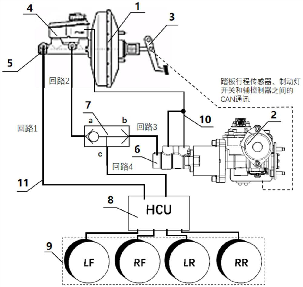
[0067] Please refer to figure 1 , this embodiment provides a hybrid brake system, including a vacuum booster assembly 1, an auxiliary electro-hydraulic servo brake assembly 2, a brake pedal 3, a liquid storage tank 4, a main brake master cylinder 5, an auxiliary system Active master cylinder 6, shuttle valve 7, hydraulic control unit (HCU) 8 and brake group 9. The two ends of the vacuum booster assembly 1 are respectively connected with the main brake master cylinder 5 and the brake pedal 3, and the brake pedal 3 in this embodiment is also equipped with a pedal stroke sensor for detecting the pedal depression stroke and for The brake light switch for detecting the pedal brake operation, the pedal travel sensor, the brake light switch and the auxiliary electro-hydraulic servo brake assembly 2 are connected through CAN bus communication. The auxiliary electro-hydraulic servo brake assembly 2 is connected with the auxiliary brake master cylinder 6 .
[0068] In this embodiment,...
Embodiment 2
[0101] The structure of the hybrid braking system in this embodiment is basically the same as that in Embodiment 1, the difference is that: the first brake group in this embodiment is composed of left rear wheel brake LR and right rear wheel brake RR; the second brake group It consists of left front wheel brake LF and right front wheel brake RF. The four oil outlets of the hydraulic control unit 8 are respectively connected with LR, RR, LF and RF. At this time, the braking system is an H-shaped arrangement.
Embodiment 3
[0103] The structure of the hybrid braking system in this embodiment is basically the same as that in Embodiment 1, the difference is that the first brake set in this embodiment consists of a left front wheel brake LF and a right rear wheel brake RR, and the second brake set It consists of the right front wheel brake RF and the left rear wheel brake LR. The four oil outlets of the hydraulic control unit 8 are respectively connected with LF, RR, RF and LR. At this time, the brake system is an X-shaped arrangement.
PUM
 Abstract
Description
Claims
Application Information
 - R&D Engineer
- R&D Manager
- IP Professional
- Industry Leading Data Capabilities
- Powerful AI technology
- Patent DNA Extraction
Browse by: Latest US Patents, China's latest patents, Technical Efficacy Thesaurus, Application Domain, Technology Topic, Popular Technical Reports.
© 2024 PatSnap. All rights reserved.Legal|Privacy policy|Modern Slavery Act Transparency Statement|Sitemap|About US| Contact US: help@patsnap.com