


Quick Research
Generate reliable direction feasibility study reports for your R&D in just a few steps.

Technical Q&A
Discover and master advanced knowledge NOW. Basics, ideas, possibilities, all at once.

Find Solutions
As an expert in R&D theories, this can generate solutions to your technical problems instantly.

Evaluate Feasibility
Analyze your overall solution with one click, know your potential R&D risks in advance.

Monitor Landscape
Get weekly tech updates, stay abreast of the latest tech innovations and key insights.
Solar street lamp equipment with intelligent charging and discharging functions
A technology for solar street lamps and equipment, applied in mechanical equipment, lighting and heating equipment, energy-saving lighting, etc., can solve the problem of inability to absorb enough light energy, and achieve the effect of solving the problem of inability to charge
- Summary
- Abstract
- Description
- Claims
- Application Information
AI Technical Summary
Problems solved by technology
Method used
Image

Examples
Embodiment 1
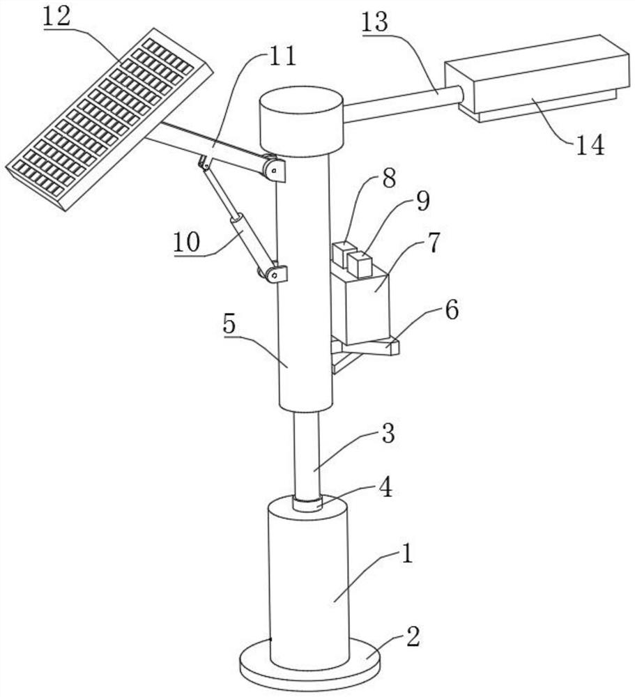
[0025] refer to Figure 1-3 , a solar street light device with intelligent charging and discharging functions, including a mounting cylinder 1, a base 2 is fixedly installed on the bottom of the mounting cylinder 1, a guide sleeve 4 is fixedly installed on the top of the installation cylinder 1, and a guide sleeve 4 is installed slidingly on the inside The sleeve rod 3, the sleeve rod 3 runs through the top wall of the installation cylinder 1, and is slidingly connected with the installation cylinder 1, the top of the sleeve rod 3 is fixedly installed with the installation rod 5, and the outside of the installation rod 5 is fixedly installed with a fixed plate 6, the fixed plate 6 A battery box 7 is fixedly installed on the top of the battery box 7, and a voltage controller 8 and a charge and discharge controller 9 are fixedly installed on the top of the battery box 7. An electric telescopic rod 10 is hinged on one side of the top of the installation rod 5, and the output end o...
Embodiment 2
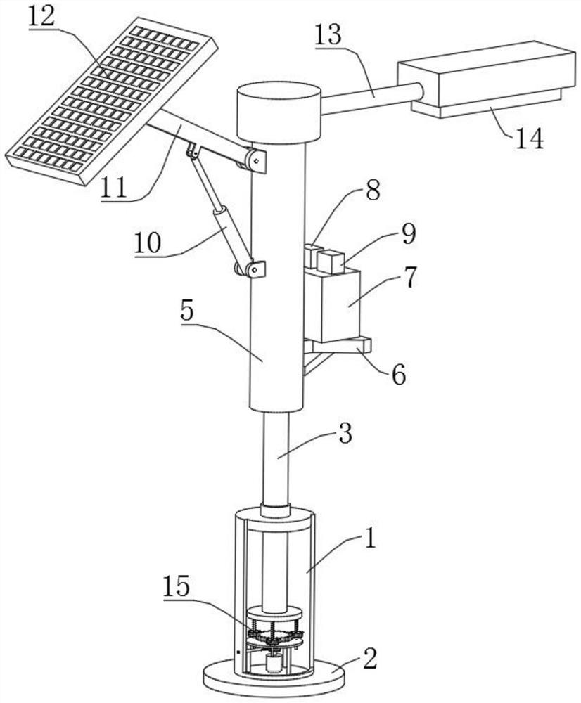
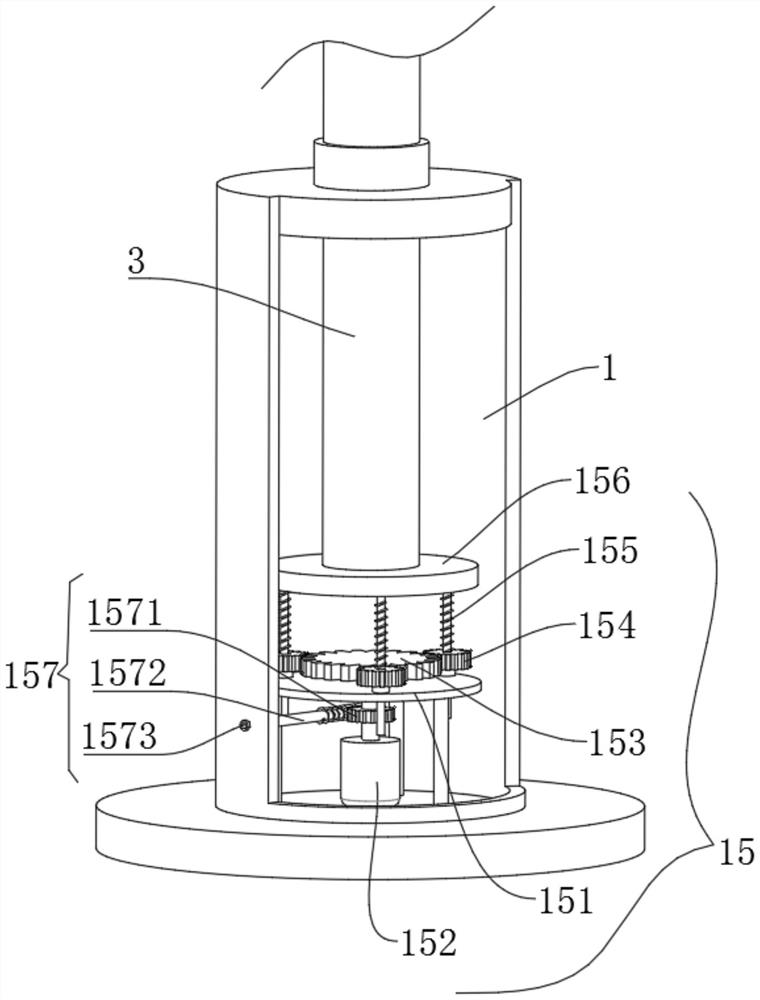
[0028] refer to Figure 1-4 , as another preferred embodiment of the present invention, the difference from Embodiment 1 is that a height adjustment mechanism 15 is installed inside the installation cylinder 1, and the height adjustment mechanism 15 includes a mounting seat 151, which is fixedly installed on the bottom of the installation cylinder 1. Inside, a driving motor 152 is fixedly installed on the bottom end of the inner side of the installation cylinder 1. The output shaft of the driving motor 152 passes through the mounting seat 151 and is rotatably connected with the mounting seat 151. The output shaft of the driving motor 152 is fixedly connected with a central gear 153. The central gear The outer edge of 153 is meshed with some gear sleeves 154, and the gear sleeves 154 are all rotatably installed on the mounting base 151. The inboard of the gear sleeve 154 is threaded with a threaded rod 155, and the threaded rod 155 runs through the mounting base 151, and is conn...
Embodiment 3
[0031] refer to Figure 1-5 , as another preferred embodiment of the present invention, the difference from Embodiment 1 or Embodiment 2 is that a transmission assembly 157 is installed at the bottom end of the central gear 153, and the transmission assembly 157 includes a worm wheel 1571 coaxial with the central gear 153 Fixed connection, one side of the worm wheel 1571 is driven with a worm 1572, and the worm 1572 is rotatably installed inside the installation cylinder 1. One end of the worm 1572 is provided with a docking groove 1573, and a corresponding docking block 18 can be inserted into the docking groove 1573. A rotating shaft 17 is fixedly installed on one end of the block 18 , and a hand wheel 16 is fixedly installed on the end of the rotating shaft 17 away from the docking block 18 .
[0032]When the power fails, the docking block 18 can be inserted into the docking groove 1573, and then the worm 1572 is driven to rotate by turning the hand wheel 16. Since the worm...
PUM
 Abstract
Description
Claims
Application Information
 - R&D Engineer
- R&D Manager
- IP Professional
- Industry Leading Data Capabilities
- Powerful AI technology
- Patent DNA Extraction
Browse by: Latest US Patents, China's latest patents, Technical Efficacy Thesaurus, Application Domain, Technology Topic, Popular Technical Reports.
© 2024 PatSnap. All rights reserved.Legal|Privacy policy|Modern Slavery Act Transparency Statement|Sitemap|About US| Contact US: help@patsnap.com