Eureka AIR delivers breakthrough ideas for toughest innovation challenges, trusted by R&D personnel around the world.

A buck-boost converter control circuit with mode switching

A buck-boost converter and control circuit technology, applied in control/regulation systems, DC power input conversion to DC power output, instruments, etc., can solve problems such as uncertain working modes

Active Publication Date: 2021-08-03
SOUTHCHIP SEMICON TECH SHANGHAI CO LTD
View PDF6 Cites 0 Cited by
  • Summary
  • Abstract
  • Description
  • Claims
  • Application Information

AI Technical Summary

Problems solved by technology

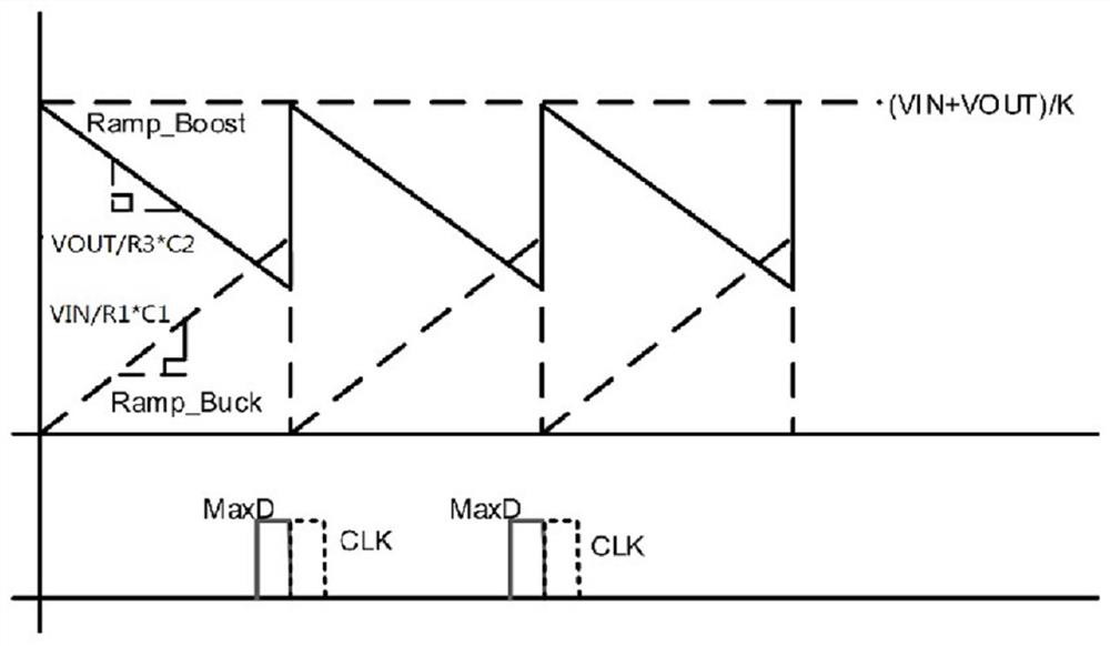
[0004] Aiming at the problem that the gap between the boost ramp signal Ramp-Boost and the buck ramp signal Ramp-Buck in the traditional buck-boost converter leads to uncertain working modes, the present invention proposes a control circuit of the buck-boost converter, which combines The control method of the present invention can realize the stable switching between the boost working mode, the step-down working mode and the buck-boost working mode of the buck-boost converter, and also proposes a corresponding feed-forward compensation scheme, which can reduce the ripple and reduce power loss

Method used


Image

  • A buck-boost converter control circuit with mode switching
  • A buck-boost converter control circuit with mode switching
  • A buck-boost converter control circuit with mode switching

Examples


Embodiment Construction

[0073] The technical solution of the present invention will be described in detail below in conjunction with the accompanying drawings and specific embodiments.

[0074] The specific details in the embodiments described below, such as the specific circuit structure in the embodiments and the specific parameters of these circuit elements, are used to provide a better understanding of the embodiments of the present invention, wherein the first and second are used to distinguish and Not intended to be limiting, such as the first state and second state of a signal. It will be understood by those skilled in the art that embodiments of the present invention may be practiced even without certain details or other combinations of methods, elements, materials, and the like.

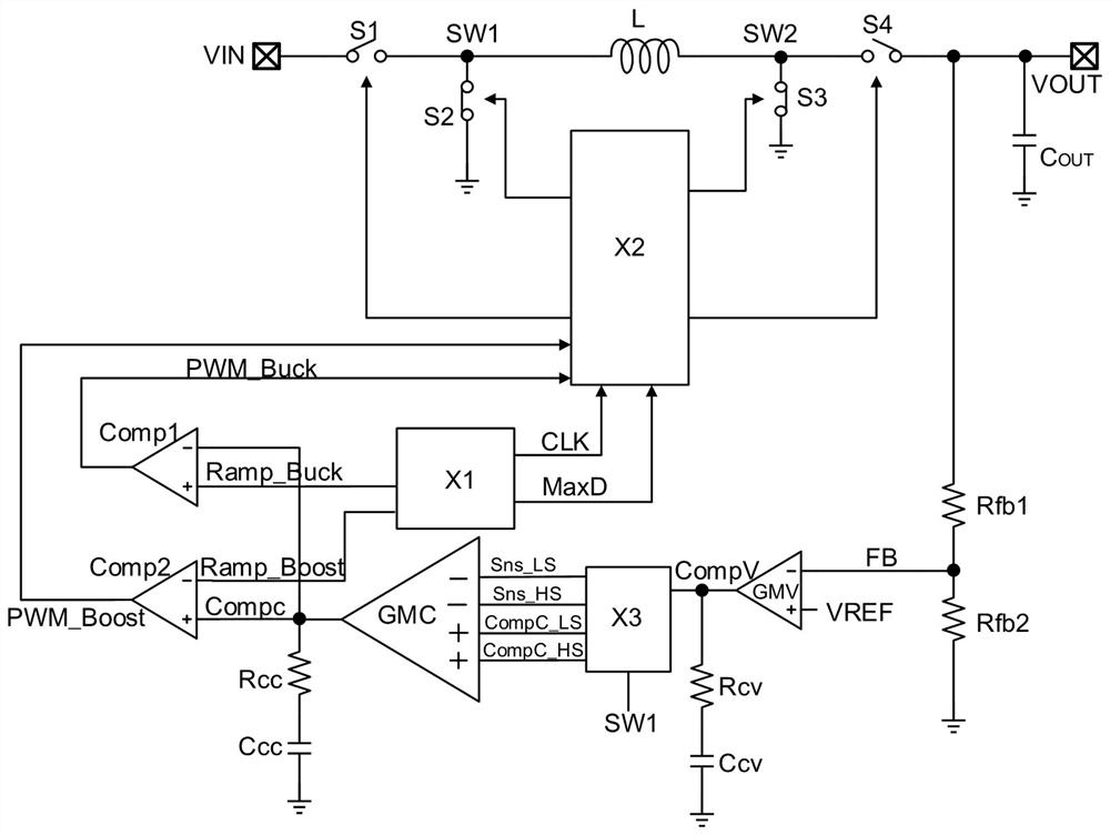
[0075] like figure 1 As shown, the buck-boost converter includes a first switch tube S1, a second switch tube S2, a third switch tube S3, a fourth switch tube S4 and an inductor L, and the first switch tube S1 and...


PUM


Abstract

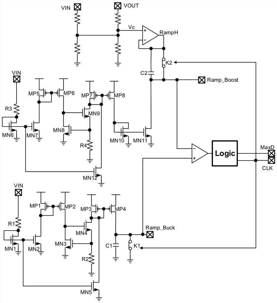
A buck-boost converter control circuit with mode switching, the first differential processing module generates an output signal according to the difference between the sampling value of the output signal of the buck-boost converter and the reference voltage; the dual-rail current sampling module samples the first differential processing The output signal of the module and the signal at the first switch node are output to the second differential processing module; the second differential processing module generates an output signal according to the difference between the output signal of the first differential processing module and the sampling value of the signal at the first switch node , and compared with the step-down ramp signal and the step-up ramp signal respectively to obtain the pulse width modulation signal of the boost control and the step-down control, where the ramp signal generation module is used to generate the step-down ramp signal and the boost ramp signal with overlapping intervals ; Finally, the logic control module generates the control signals of the four switch tubes in the buck-boost converter to control the buck-boost converter to work in the corresponding working mode; the embodiment also proposes the feedforward for entering and exiting the buck-boost working interval compensation package.

Description

technical field [0001] The invention belongs to the technical field of voltage-boost circuit control in an average current mode, and relates to a control circuit and a control method of a voltage-boost converter, which can realize mode switching and feedforward compensation. Background technique [0002] like figure 1 The switch tubes S1-S4, inductor L and output capacitor C shown OUT A buck-boost converter is formed, and the buck-boost converter is used to convert the input voltage VIN into an output voltage VOUT, including a boost mode, a buck mode and a buck-boost mode. Specifically, the buck-boost converter generates corresponding pulse width modulation signals PWM_Buck and PWM_Boost according to the two ramp signals Ramp-Buck and Ramp-Boost, which are used to control the switch tubes S1-S4. In the step-down operation, the input voltage VIN Higher than the output voltage VOUT, the switches S1 and S3 are turned on, S2 and S4 are turned off, and the inductor L stores ene...

Claims


Application Information

Patent Timeline
Patent Type & Authority Patents(China)
IPC IPC(8): H02M3/156H02M3/158H02M1/14
CPCH02M1/14H02M3/156H02M3/1582
Inventor 耿翔卞坚坚
Owner SOUTHCHIP SEMICON TECH SHANGHAI CO LTD
Why Eureka
Eureka Blog
Learn More