Focus calibration system and focus calibration method based on light beam scanning angle modulation

A calibration system, beam scanning technology, applied in the field of optics, to achieve the effect of high calibration accuracy

Pending Publication Date: 2021-06-18
HARBIN INST OF TECH
View PDF0 Cites 2 Cited by
  • Summary
  • Abstract
  • Description
  • Claims
  • Application Information

AI Technical Summary

Problems solved by technology

[0007] The purpose of the present invention is to propose a focus calibration system and a focus calibration method based on light beam scanning angle modulation to solve the problems in the prior art

Method used


Image

  • Focus calibration system and focus calibration method based on light beam scanning angle modulation
  • Focus calibration system and focus calibration method based on light beam scanning angle modulation
  • Focus calibration system and focus calibration method based on light beam scanning angle modulation

Examples


Embodiment Construction

[0040] The technical solutions in the embodiments of the present invention will be clearly and completely described below in conjunction with the accompanying drawings in the embodiments of the present invention. Obviously, the described embodiments are only some, not all, embodiments of the present invention. Based on the embodiments of the present invention, all other embodiments obtained by persons of ordinary skill in the art without making creative efforts belong to the protection scope of the present invention.

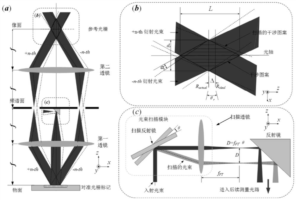
[0041] A phase grating alignment system can be viewed as a two-lens 4f system, with the reference grating directly behind the image plane, as in figure 1 shown.

[0042] figure 1 (a) illustrates the effect of defocus. When the beam illuminates the alignment marks of the alignment grating, it produces +n and -n order reflections, which create an interference pattern in the object plane. The interference pattern is projected onto the image plane, resulting in a...


PUM


Abstract

The invention discloses a focus calibration system and a focus calibration method based on light beam scanning angle modulation, and belongs to the technical field of optics. The invention proposes a theoretical model that describes the amplitude of a focus calibration signal that is measured after the reference grating using phase sensitive detection as a function of the alignment grating mark z position. According to the focus calibration system and the focus calibration method based on light beam scanning angle modulation, the method has the advantages that the z-direction position of the grating mark can be accurately determined through the self measurement performance of the alignment measurement system, and the situation that z-direction calibration needs to be carried out through other sensors of a photoetching system in the prior art is changed. According to the method, the focus calibration precision of the alignment measurement system is high, the sub-nanometer level can be achieved, algorithm support is provided, and adjustment is more accurate.

Description

technical field [0001] The invention relates to a focus calibration system and a focus calibration method based on light beam scanning angle modulation, belonging to the field of optical technology. Background technique [0002] The process node of integrated circuits has been developed to 10nm and smaller. The demand for integrated circuit manufacturing is a huge driving force for the development of lithography technology. Due to the use of complex patterns, especially when using multiple patterning techniques and advanced materials, the demands on cladding are increasing. This creates an urgent need for ultra-high precision photolithographic alignment. [0003] The key subsystem of the lithography equipment is the lithography alignment measurement system, which ensures the positional accuracy of each layer in multilayer lithography by measuring the exact position of the alignment marks. Its measurement performance will directly determine the characteristics of the litho...

Claims


Application Information

Patent Timeline
IPC IPC(8): G03F7/20
CPCG03F7/70358G03F7/70241G03F7/70233G03F7/70316G03F7/70541
Inventor 张韬马亚蕊王辉
Owner HARBIN INST OF TECH
Why Eureka
Try Eureka