Self-powered DC voltage measurement control circuit and measurement device

A DC voltage, measurement and control technology, applied in measurement devices, measurement of electrical variables, measurement of current/voltage, etc., can solve problems such as increasing system cost and complexity, limiting measurement accuracy and measurement range, and large temperature drift coefficient. Improve measurement accuracy and measurement range, reduce cost and space, and reduce the effect of measurement temperature drift

Active Publication Date: 2021-06-18
NINGBO CRRC TIMES TRANSDUCER TECH CO LTD
View PDF9 Cites 0 Cited by
  • Summary
  • Abstract
  • Description
  • Claims
  • Application Information

AI Technical Summary

Problems solved by technology

At present, the DC voltage measurement device mainly adopts the magnetic balance principle, magnetic modulation principle, photoelectric isolation, digital isolation and other methods to realize the isolated measurement of DC high voltage. These methods need to provide a separate standard power supply; the introduction of the standard power supply will increase the cost of the system and complexity, especially in the transformation of existing sites, it is difficult to increase the standard power supply and power supply connection lines due to structural limitations, which limits the application of this type of sensor
[0003] The current passive DC voltage measuring device has defects such as large temperature drift coefficient and poor mechanical vibration performance, and because the passive DC voltage measuring device adopts a single resistance voltage divider, the current consumption of the oscillation circuit will limit its measurement accuracy and measurement range

Method used


Image

  • Self-powered DC voltage measurement control circuit and measurement device
  • Self-powered DC voltage measurement control circuit and measurement device
  • Self-powered DC voltage measurement control circuit and measurement device

Examples


Embodiment Construction

[0027] The following are specific embodiments of the present invention and in conjunction with the accompanying drawings, the technical solutions of the present invention are further described, but the present invention is not limited to these embodiments.

[0028] It should be noted that all directional indications (such as up, down, left, right, front, back...) in the embodiments of the present invention are only used to explain the relationship between the components in a certain posture (as shown in the figure). Relative positional relationship, movement conditions, etc., if the specific posture changes, the directional indication will also change accordingly.

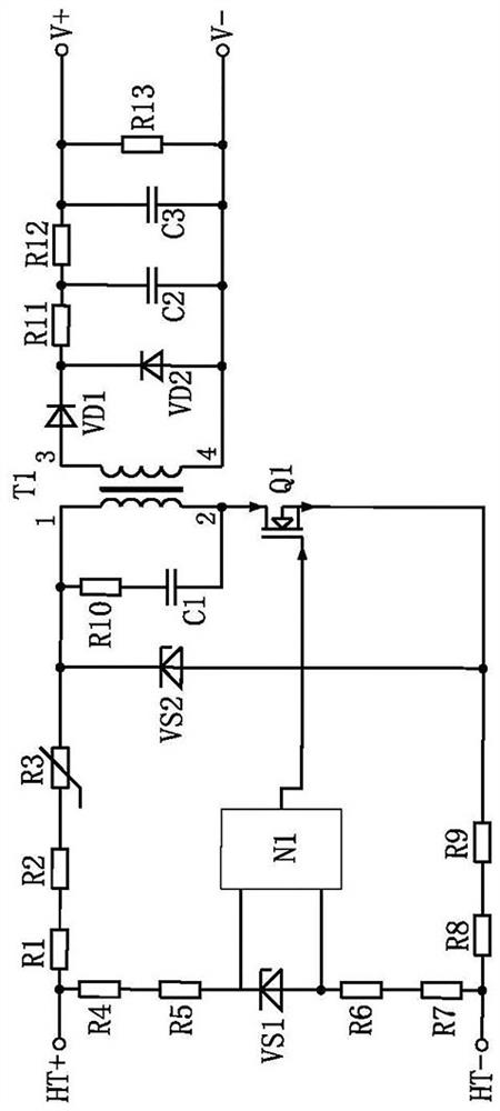
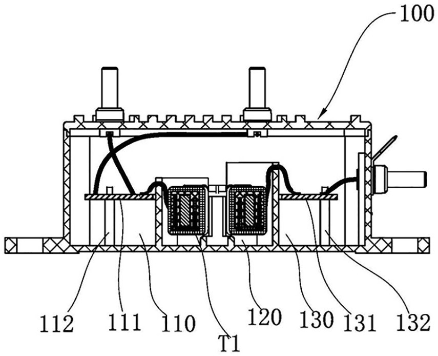
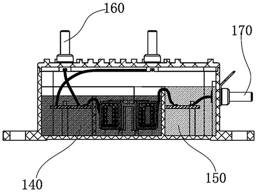
[0029] Such as Figure 1 to Figure 3 As shown, the present invention provides a self-powered DC voltage measurement control circuit, including: a primary side module, which is used to generate a corresponding current signal according to an input high-voltage signal, and output a current signal and an oscillation si...


PUM


Abstract

The invention provides a self-powered DC voltage measurement control circuit and a measurement device, and belongs to the technical field of voltage measurement, and the self-powered DC voltage measurement control circuit comprises: a primary side module which is used for generating a corresponding current signal according to an input high-voltage signal and outputting the current signal and an oscillation signal; a voltage transformation module which is connected with the primary side module and converts a high-voltage signal into a low-voltage signal according to the oscillation signal; and an output module whcih is connected with the voltage transformation module and is used for rectifying and filtering the low-voltage signal and then outputting the low-voltage signal. According to the self-powered DC voltage measurement control circuit provided by the invention, a double-path voltage division circuit is adopted, the oscillating circuit is independently powered through the second voltage division circuit, a self-powered function is realized, an additional external power supply is not needed, and the use cost and space are greatly reduced; meanwhile, the influence of the current consumption of the oscillating circuit on the overall measurement precision and the measurement range is avoided, and the measurement precision and the measurement range are improved.

Description

technical field [0001] The invention belongs to the technical field of voltage measurement, in particular to a self-powered DC voltage measurement control circuit and a measurement device. Background technique [0002] In the application of high-power DC power supply, the system needs to isolate, measure and control the DC high voltage. At present, the DC voltage measurement device mainly adopts the magnetic balance principle, magnetic modulation principle, photoelectric isolation, digital isolation and other methods to realize the isolated measurement of DC high voltage. These methods need to provide a separate standard power supply; the introduction of the standard power supply will increase the cost of the system And complexity, especially in the transformation of the existing site, it is difficult to increase the standard power supply and power supply connection lines due to structural limitations, which limits the application of this type of sensor. [0003] The curren...

Claims


Application Information

Patent Timeline
Patent Type & Authority Applications(China)
IPC IPC(8): G01R19/00
CPCG01R19/0084
Inventor 刘家豪郑民郑良广郑华雄任浩
Owner NINGBO CRRC TIMES TRANSDUCER TECH CO LTD
Why Eureka
Try Eureka