
A kind of geotechnical engineering fault fissure rock mass grouting equipment

A technology of fractured rock mass and geotechnical engineering, applied in the direction of infrastructure engineering, construction, sheet pile wall, etc. The effect of strengthening strength and reducing pulp consumption

Active Publication Date: 2022-07-26
CHUZHOU UNIV
View PDF7 Cites 0 Cited by
  • Summary
  • Abstract
  • Description
  • Claims
  • Application Information

AI Technical Summary

Problems solved by technology

[0003] However, during the long-term use, it is found that the existing grouting equipment still has certain disadvantages: 1. Due to the complex stratum conditions, there will be faults and cracks inside, if the calibration position is just at the position corresponding to the faults , it will cause the mortar to be lost into the fault during the grouting process, and the amount of grout to fill all the fault fissures will be quite large, and if the grouting space is too large, the rapid-setting expansion grout will be filled unevenly in the hole And there is a leakage cavity, which affects the support and reinforcement strength; 2. During the grouting process, the anchor rod is inserted in the grouting hole by laying it down, and the inner wall of the hole is blocked at the grouting outlet at the lower end. Under a certain pressure, the number of effective grout outlets in the grouting space is insufficient, especially for rock foundation conditions with faults and fissures, the grouting speed is very slow

Method used


Image

  • A kind of geotechnical engineering fault fissure rock mass grouting equipment
  • A kind of geotechnical engineering fault fissure rock mass grouting equipment
  • A kind of geotechnical engineering fault fissure rock mass grouting equipment

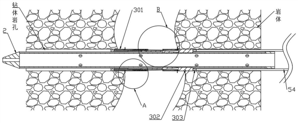
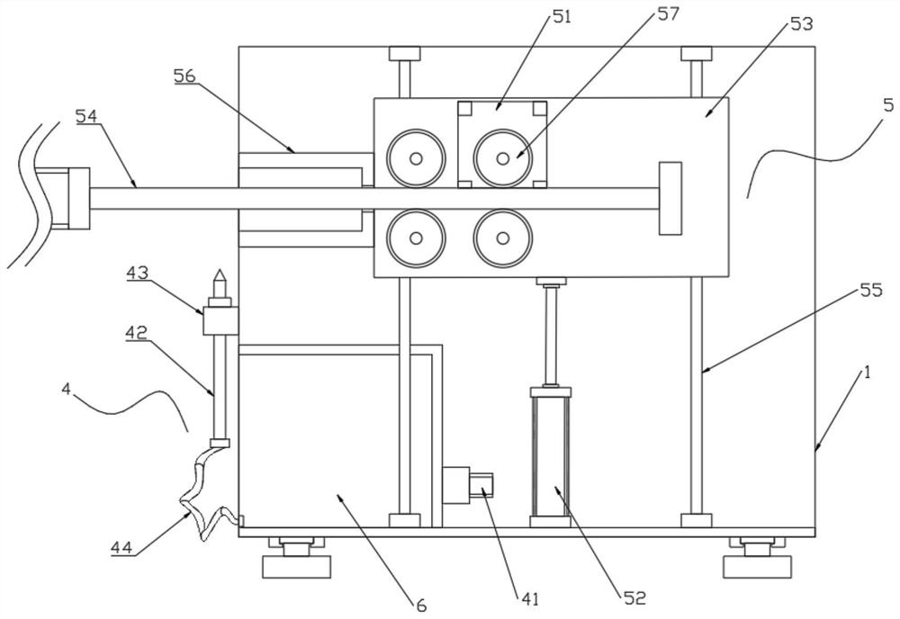
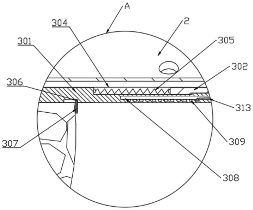
Examples


Embodiment Construction

[0023] In order to make the technical means, creative features, achievement goals and effects realized by the present invention easy to understand, the present invention will be further described below with reference to the specific embodiments.

[0024] like Figure 1 to Figure 6 As shown, a geotechnical engineering fault fissure rock mass grouting equipment includes a trolley 1, an anchor rod 2, a partition 3, a grouting mechanism 4 and a jacking mechanism 5. The interior of the trolley 1 is provided with a slurry storage chamber 6. The grouting mechanism 4 is installed on the slurry chamber 6 and is used to inject mortar into the drilling hole of the rock mass. In terms of application height, the partition part 3 is sleeved on the bolt 2 and used to prevent the slurry from spreading in the crack of the rock fault.

[0025] In this embodiment, the reinforcing slurry used is fluidized mortar, and a quick-setting agent and a micro-expansion agent are added inside.

[0026] I...


PUM


Abstract

The invention discloses a grouting equipment for rock mass of faults and fissures in geotechnical engineering, which relates to the technical field of geotechnical engineering. A slurry chamber, the grouting mechanism is installed on the slurry chamber, and is used for injecting mortar into the rock hole of the drilling body. In the present invention, a partition is sleeved on the anchor rod, and the fault cracks in the openings are blocked by the spacer 1 and the spacer two pairs of adjustable spacing, so as to avoid the flow and diffusion of the slurry at this place, and can realize the adjustment of any spacing. All faults and cracks can be effectively grouted, which greatly reduces the required grouting consumption; by setting a jacking mechanism on the trolley, the inner wall of the opening and the grouting outlet at the lower end of the anchor rod are separated, and an appropriate grouting gap is generated. The fluidized mortar can effectively flow out from all the grouting holes, and the grouting efficiency is improved. At the same time, the lifting and lowering of the lifting seat can also realize grouting for the drilling body rock holes of different heights.

Description

technical field [0001] The invention relates to the technical field of geotechnical engineering, in particular to a grouting device for rock mass grouting of faults and fissures in geotechnical engineering. Background technique [0002] The rock foundation support treatment is the support, reinforcement and protection measures used in the construction of the underground structure and the surrounding environment in the geotechnical engineering. Usually, the rock drilling machine is used to open the hole at the calibrated position, and then the flow is injected into the hole through the bolt. It can effectively improve the stability of the supporting structure through the diffusion of the slurry and the consolidation in the hole. [0003] However, in the long-term use process, it is found that the existing grouting equipment still has certain drawbacks: 1. Due to the complex formation conditions, there will be working conditions such as faults and fissures in the interior. If ...

Claims


Application Information

Patent Timeline
Patent Type & Authority Patents(China)
IPC IPC(8): E02D15/04E02D5/74
CPCE02D15/04E02D5/74E02D2250/003E02D2600/30E02D2300/0001
Inventor 李孝雄邸云菲张文超袁枫斌刘江
Owner CHUZHOU UNIV
Learn More