
Annealing device and working method thereof

An annealing device and annealing chamber technology, applied in chemical instruments and methods, crystal growth, diffusion/doping, etc., can solve problems such as temperature unevenness, and achieve the effects of improving uniformity, avoiding adverse effects, and avoiding insufficient annealing degree

Inactive Publication Date: 2021-06-18
SUZHOU EVERBRIGHT PHOTONICS CO LTD +1
View PDF5 Cites 0 Cited by
  • Summary
  • Abstract
  • Description
  • Claims
  • Application Information

AI Technical Summary

Problems solved by technology

[0004] Therefore, the technical problem to be solved by the present invention is to overcome the defect of uneven temperature at different positions in the main body of the existing annealing chamber, thereby providing an annealing device and its working method

Method used


Image

  • Annealing device and working method thereof
  • Annealing device and working method thereof
  • Annealing device and working method thereof

Examples


Embodiment 1

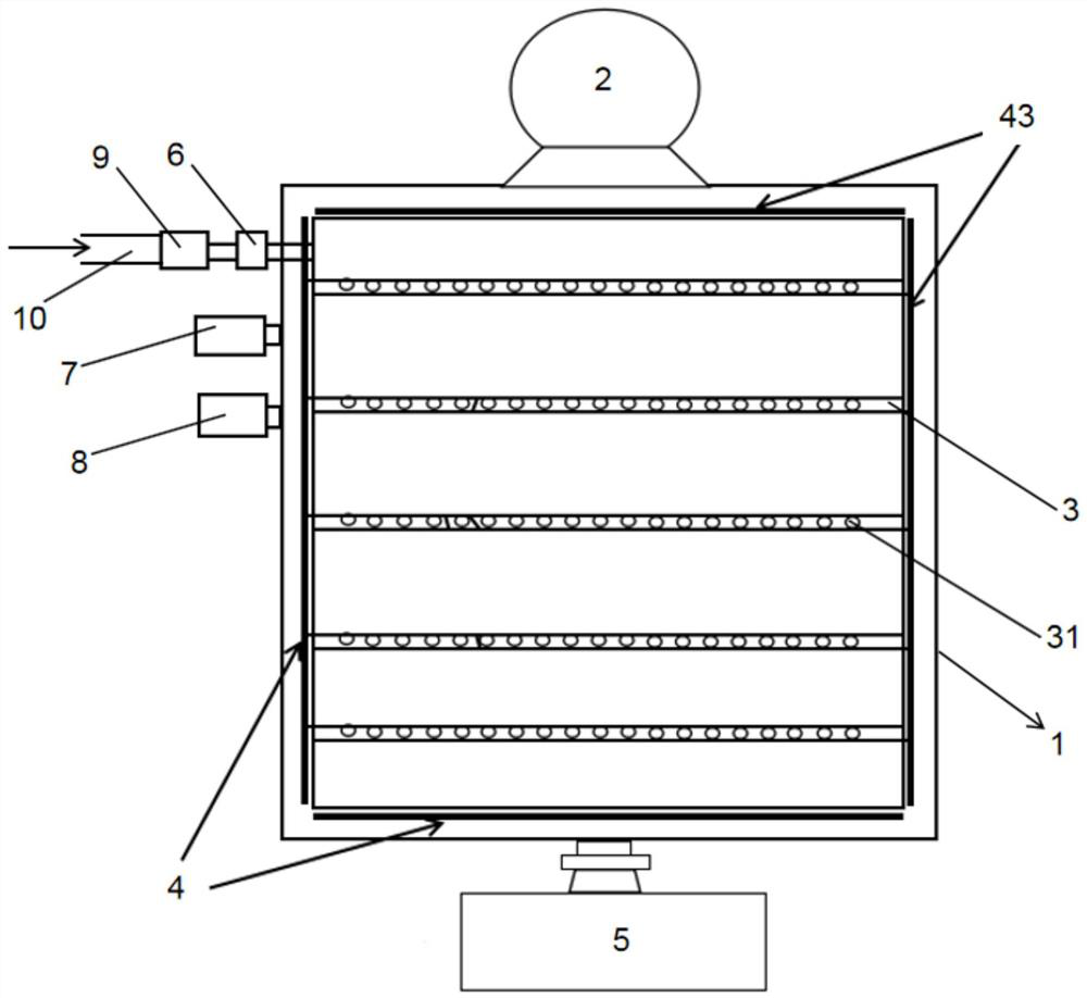
[0035] Such as figure 1 As shown, this embodiment provides an annealing device, including: an annealing chamber main body 1; an air circulation fan 2 arranged outside the annealing chamber main body 1, the air circulation fan 2 includes a rotating part and is arranged on the rotating part The outer shell is in sealing communication with the annealing chamber main body 1 .

[0036] In the above-mentioned annealing device, during the annealing process, the rotating member rotates to drive the airflow in the annealing chamber main body 1, so that heat exchange occurs at different positions in the annealing chamber main body 1, thereby improving the temperature of the annealing chamber main body 1. The uniformity of temperature at different positions avoids insufficient annealing degree of the parts to be annealed due to the low temperature in some areas of the annealing chamber main body 1, and avoids adverse effects on the performance of the semiconductor chip; at the same time,...

Embodiment 2

[0058] This embodiment provides a working method of an annealing device, using the annealing device provided in Embodiment 1, the working method of the annealing device includes the step of turning on the air circulation fan 2, and rotating the rotating member to disturb the housing and The airflow in the main body 1 of the annealing chamber. Through the above working method, the heat at different positions in the annealing chamber main body 1 is exchanged, thereby improving the uniformity of temperature at different positions in the annealing chamber main body 1, and avoiding the low temperature in some areas of the annealing chamber main body 1. As a result, the annealing degree of the parts to be annealed in this region is insufficient, and the performance of the semiconductor chip is avoided from being adversely affected.

[0059] In this embodiment, the working method of the annealing device further includes: the temperature sensor 18 obtains the actual temperature inform...


PUM

PropertyMeasurementUnit
pore sizeaaaaaaaaaa

Abstract

The invention provides an annealing device and a working method thereof. The annealing device comprises an annealing cavity body and an airflow circulating fan, the airflow circulating fan is arranged outside the annealing cavity body, the airflow circulating fan comprises a rotating part and a shell arranged on the outer side of the rotating part, and the shell is in sealing communication with the annealing cavity body. In the annealing process, the rotating part rotates to drive airflow in the annealing cavity body to flow, so that heat at different positions in the annealing cavity body is exchanged, and the temperature uniformity of the different positions in the annealing cavity body is improved. Meanwhile, the airflow circulating fan is arranged outside the annealing cavity body and does not occupy the internal space of the annealing cavity body, so that the number of to-be-annealed parts which can be annealed simultaneously is increased, and the annealing efficiency is improved.

Description

technical field [0001] The invention relates to the technical field of annealing equipment, in particular to an annealing device and a working method thereof. Background technique [0002] In the manufacturing process of semiconductor chips, high-temperature annealing is usually performed after ion implantation and doping. This is because when impurity ions are implanted into the semiconductor, the high-energy incident ions will collide with the atoms on the semiconductor lattice, causing some lattice atoms to be displaced, resulting in a large number of vacancies, which makes the arrangement of atoms in the implanted region disordered or changed. Therefore, after ion implantation, the semiconductor must be annealed at a certain temperature to restore the crystal structure and eliminate defects. At the same time, annealing also has the function of activating the donor and acceptor impurities, that is, the impurity atoms in the interstitial position can enter the replacement...

Claims


Application Information

Patent Timeline
Patent Type & Authority Applications(China)
IPC IPC(8): C30B33/02C30B31/22
CPCC30B33/02C30B31/22
Inventor 龚来俊储沼泽王俊刘恒李泉灵
Owner SUZHOU EVERBRIGHT PHOTONICS CO LTD
Learn More