
Sheet inserting mechanism and groove position structure for sheet inserting mechanism

A technology for inserting slots and inserts, which is applied in the direction of conveyor objects, ceramic molding machines, unloading devices, etc., can solve the problems of low work efficiency, waste of manpower and working hours, etc., to save manpower and hours, solve manpower and The effect of working hours and easy cleaning

Inactive Publication Date: 2021-06-18
GUANGZHOU HAIGU ELECTRONICS TECH
View PDF11 Cites 1 Cited by
  • Summary
  • Abstract
  • Description
  • Claims
  • Application Information

AI Technical Summary

Problems solved by technology

[0003] The purpose of the present invention is to provide an inserting mechanism and a slot structure for the inserting mechanism, which solves the problem that the inserting mechanism of the current inserting machine needs to waste a lot of manpower and man-hours, and the work efficiency of the inserting is low. problems, and improving the slot for easy cleaning, disassembly, repair, and replacement

Method used

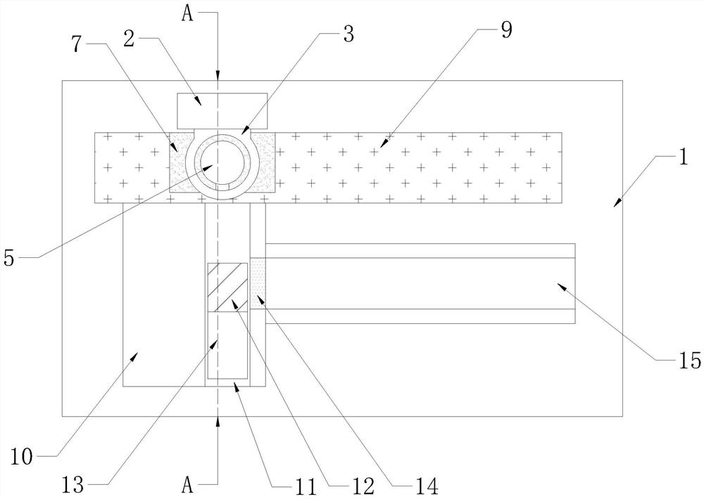
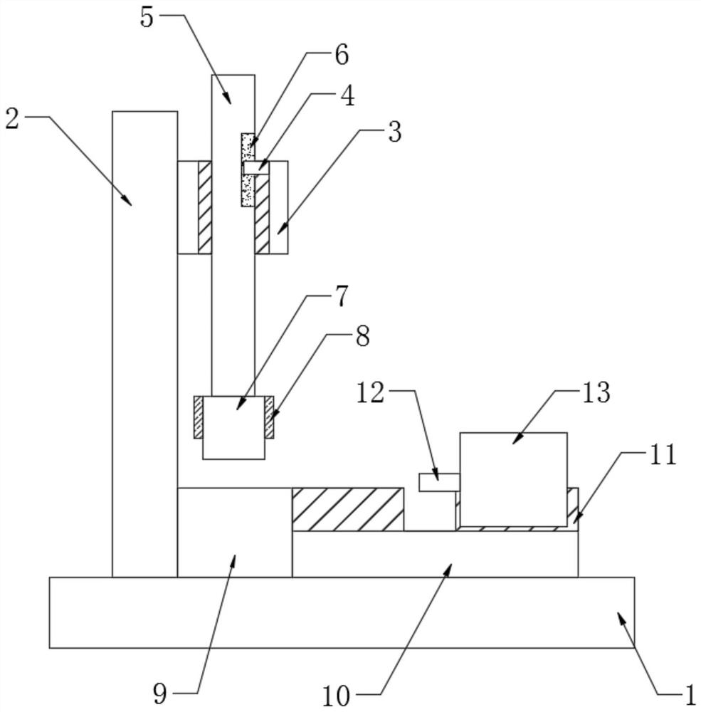
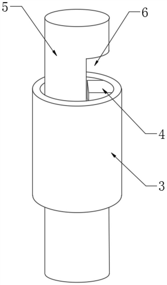

Image

  • Sheet inserting mechanism and groove position structure for sheet inserting mechanism
  • Sheet inserting mechanism and groove position structure for sheet inserting mechanism
  • Sheet inserting mechanism and groove position structure for sheet inserting mechanism

Examples


Embodiment Construction

[0036] In order to make the technical means, creative features, goals and effects achieved by the present invention easy to understand, the present invention will be further described below in conjunction with specific embodiments.

[0037] In describing the present invention, it should be understood that the terms "upper", "lower", "front", "rear", "left", "right", "top", "bottom", "inner", " The orientation or positional relationship indicated by "outside", etc. is based on the orientation or positional relationship shown in the drawings, and is only for the convenience of describing the present invention and simplifying the description, rather than indicating or implying that the referred device or element must have a specific orientation, so as to Specific orientation configurations and operations, therefore, are not to be construed as limitations on the invention.

[0038] In the description of the present invention, it should be noted that, unless otherwise specified and...


PUM


Abstract

The invention discloses a sheet inserting mechanism and a groove position structure for the sheet inserting mechanism. The sheet inserting mechanism comprises a working table plate and a tape conveying plate, wherein a supporting rod is fixedly mounted on one side of the top end of the working table plate; a limiting lantern ring is welded to the upper end of the supporting rod; a pressing rod is sleeved with the limiting lantern ring; a glue pressing block is fixedly mounted at the bottom end of the pressing rod; the side, away from the supporting rod, of the tape conveying plate is provided with a sheet inserting groove seat; the sheet inserting groove seat is fixedly connected with the working table plate; one side of the top end of the sheet inserting groove seat is provided with a sliding groove; the sliding groove and the tape conveying plate are arranged in a mutually perpendicular mode; and the groove position structure of the sliding groove is a detachable structure. The sheet inserting mechanism is novel in structure, the problem that the sheet inserting working efficiency is low since a large amount of manpower and working hours are wasted by the sheet inserting mechanism of an existing sheet inserting machine is effectively solved, and the groove position structure is lifted to facilitate cleaning, dismounting, mounting, repairing and replacement.

Description

technical field [0001] The invention relates to the technical field of chip insertion machines, in particular to a chip insertion mechanism and a slot structure for the chip insertion mechanism. Background technique [0002] For the processing of ceramic sensors, first insert the pins on the ceramic sheet, and then enter the ground welding and other processing. When the current inserting machine inserts the ceramic sheet and the pin bracket, it needs to manually load the ceramic sheet, resulting in It needs to waste a lot of manpower and man-hours, and the work efficiency of its insertion is low. In addition, when the machine is used for long-term processing, some ceramic chips will be squeezed and broken, so the debris needs to be cleaned, which is inconvenient to clean and affects the later stage. In order to solve this problem, we propose an insertion mechanism and a slot structure for the insertion mechanism. Contents of the invention [0003] The purpose of the prese...

Claims


Application Information

Patent Timeline
Patent Type & Authority Applications(China)
IPC IPC(8): B65G49/08H01F41/00
CPCB65G49/08H01F41/00
Inventor 许赵武何锦标梁锦文
Owner GUANGZHOU HAIGU ELECTRONICS TECH
Learn More