A laser scanning-based electrified railway limit detection method and system
An electrified railway and laser scanning technology, applied in the field of measurement, can solve problems such as low operation efficiency and complex overall process, and achieve the effect of ensuring accuracy, enhancing effect, and eliminating accumulated errors
- Summary
- Abstract
- Description
- Claims
- Application Information
AI Technical Summary
Problems solved by technology
Method used
Image
Examples
Embodiment 1
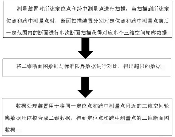
[0060] In an exemplary embodiment, a laser scanning-based electrified railway limit detection method is provided, which is used to detect the limit of the electrified railway catenary. The detection device is built on a detection platform, and the detection platform can be placed on the rail Free movement, several positioning points are set around the railway, and a mid-span measurement point is set at a certain distance between two adjacent positioning points; the detection device includes a measuring device, a section scanning device and a data processing device, such as figure 1 As shown, the method includes the following steps:
[0061] The measuring device scans the positioning point and the mid-span measuring point, and when the positioning point is scanned, the cross-sectional scanning device performs multiple cross-sectional scanning on the cross-sections within a certain range before and after the positioning point to obtain corresponding multiple three-dimensional spa...
Embodiment 2
[0070] This embodiment has the same inventive concept as Embodiment 1. On the basis of Embodiment 1, a specific method for cross-sectional scanning is provided. The detection device also includes a photographing device, and the photographing device captures a panoramic image of the current scanning section. Specifically, after obtaining the three-dimensional space contour data at the current positioning point, let the detection platform continue to move forward for a certain distance, and take a panoramic high-definition image of the current scanning section. The function of taking a picture is to associate a High-definition images are used for storage, playback, analysis, and management of the actual situation at the section view.
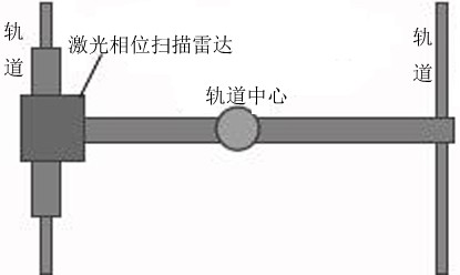
[0071] The section scanning device is a laser phase scanning radar, such as figure 2 As shown, the laser phase scanning radar is located on the rail on one side of the railway.
[0072] The laser phase scanning radar scans and measures the cross...
Embodiment 3
[0088] Specifically, using the hand-push measuring trolley as the detection platform can realize the patrol inspection of any section of the line, which solves the problem that the current vehicle-mounted limit detection device is easily restricted by organized traffic, and at the same time, the electrified railway limit intelligent measuring instrument does not need to be dispatched For rail cars, inspection operations can be carried out only by blocking the inspection area. It is simple and efficient to use the hand-push measuring trolley, and after the section is blocked, it can continuously detect the electrified railway limit at a speed of 0-5km / h, which greatly improves the efficiency of manual measurement.
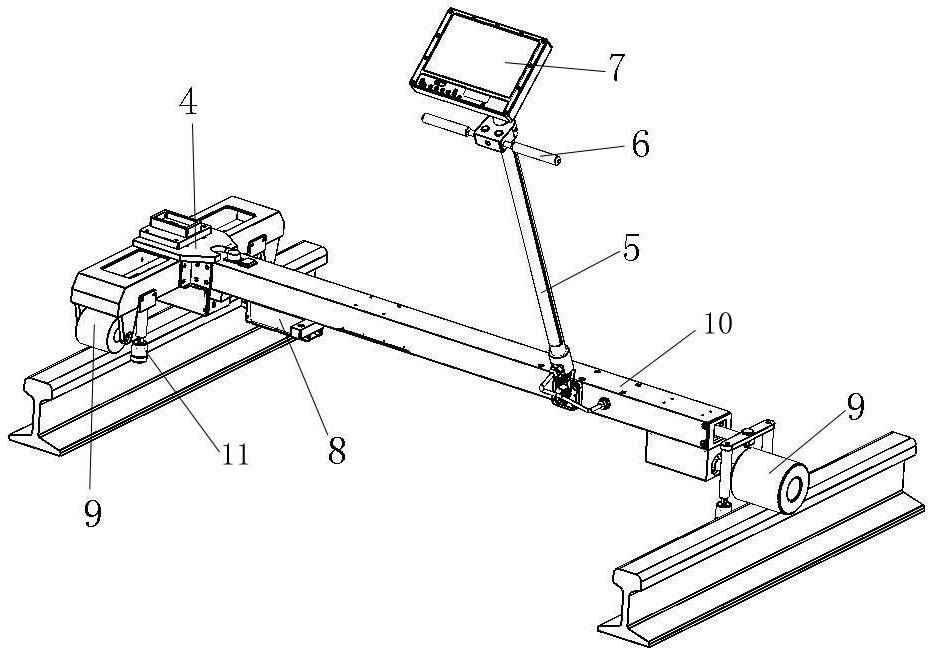
[0089] Specifically, such as Figure 4As shown, in an embodiment, a specific structural diagram of the measuring trolley is provided, including a telescopic walking frame 10, and the walking frame 10 can also directly adopt an existing telescopic rod, that is, the w...
PUM
 Abstract
Description
Claims
Application Information
 - R&D
- Intellectual Property
- Life Sciences
- Materials
- Tech Scout
- Unparalleled Data Quality
- Higher Quality Content
- 60% Fewer Hallucinations
Browse by: Latest US Patents, China's latest patents, Technical Efficacy Thesaurus, Application Domain, Technology Topic, Popular Technical Reports.
© 2025 PatSnap. All rights reserved.Legal|Privacy policy|Modern Slavery Act Transparency Statement|Sitemap|About US| Contact US: help@patsnap.com


