Ophthalmic examination device
A technology of ophthalmological examination and pen holder, which is applied in medical science, equipment for testing eyes, diagnosis, etc., and can solve the problem of single functionality of ophthalmic examination devices
Pending Publication Date: 2021-06-18
成都市第三人民医院
View PDF0 Cites 1 Cited by
- Summary
- Abstract
- Description
- Claims
- Application Information
AI Technical Summary
Problems solved by technology
[0003] The object of the present invention is to provide an ophthalmic examination device to solve the problem of single functionality of the ophthalmic examination device in the prior art
Method used
View moreImage
Smart ImageViewing Examples
Examples
Embodiment
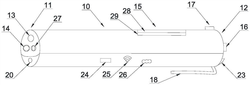
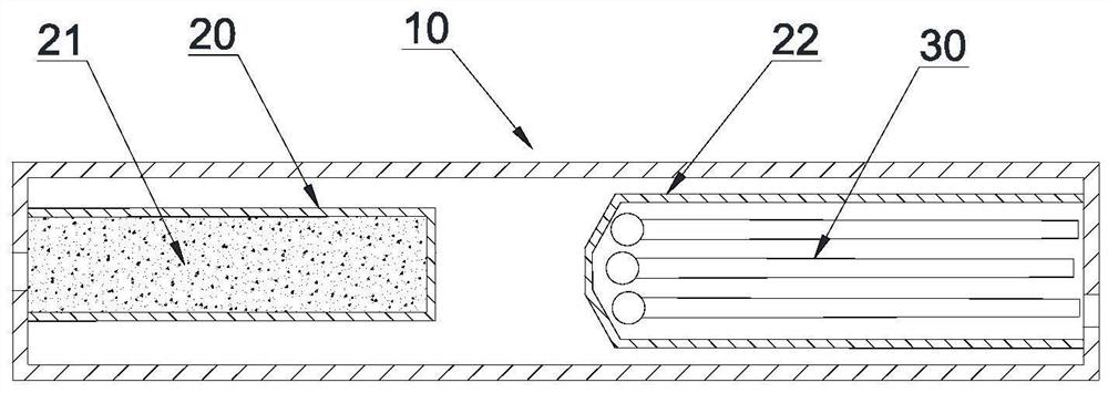
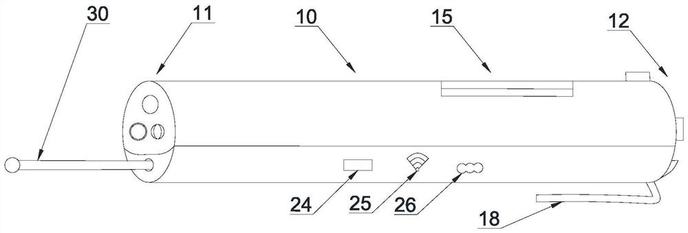
[0033] refer to figure 1 , an ophthalmic inspection device, comprising: an inspection pen holder 10 and an imaging element arranged inside the inspection pen holder 10 .
Login to View More PUM
 Abstract
The invention discloses an ophthalmic examination device, and belongs to the technical field of medical auxiliary articles. The ophthalmic examination device comprises an examination pen container and an imaging element arranged in the examination pen container; the examination pen container comprises an examination end and a handheld end; the examination end is provided with an illuminating lamp and a camera in communication connection with the imaging element; a display screen is arranged on the outer side of the examination pen container; the display screen comprises a first screen and a second screen which is located below the first screen and coincides with the first screen; a comparison diagram is displayed in the first screen; the second screen is in communication connection with the imaging element; and the handheld end is provided with a first switch in communication connection with the illuminating lamp and a second switch in communication connection with the camera, the imaging element and the second screen. The examination end of the ophthalmic examination device is provided with the illuminating lamp and the camera to examine the pupil of a patient, the actual size of the pupil is displayed with the cooperation of the imaging element and the display screen, and a pupil image is compared with the comparison diagram, thereby solving the problem that an existing ophthalmic examination device is single in function.
Description
technical field [0001] The invention relates to the technical field of medical auxiliary articles, in particular to an ophthalmic examination device. Background technique [0002] Nervous system ophthalmology examination includes pupillary examination (pupil shape, size, direct and indirect light reflex), corneal reflex, and eyelash reflex, which reflect the damage on the relevant nerve conduction pathways, and can be used for the diagnosis of neurological patients and the judgment of disease severity It is very important and is one of the routine required inspection items. But usually a doctor needs to use a variety of tools for examination, such as flashlight, pupil monitor, cotton swab, etc., and occasionally needs to control the opening and closing of the patient's eyelids by hand. The whole process is relatively complicated. Therefore, the prior art has the problem of single functionality of the ophthalmic examination device. Contents of the invention [0003] The o...
Claims
Login to View More Application Information
Patent Timeline
 IPC IPC(8): A61B3/18A61B3/11A61B3/02
CPCA61B3/0008A61B3/0041A61B3/02A61B3/112A61B3/18
Inventor 何柳
Owner 成都市第三人民医院
Features
- R&D
- Intellectual Property
- Life Sciences
- Materials
- Tech Scout
- Unparalleled Data Quality
- Higher Quality Content
- 60% Fewer Hallucinations
Learn More Browse by: Latest US Patents, China's latest patents, Technical Efficacy Thesaurus, Application Domain, Technology Topic, Popular Technical Reports.
© 2025 PatSnap. All rights reserved.Legal|Privacy policy|Modern Slavery Act Transparency Statement|Sitemap|About US| Contact US: help@patsnap.com


