Cathode flow field plate structure of air-cooled fuel cell and air-cooled fuel cell

A fuel cell and cathode flow field technology, applied in fuel cells, fuel cell additives, fuel cell heat exchange, etc., can solve the problems of proton conductivity drop, battery performance drop, battery current density drop, etc., to improve proton conductivity efficiency, efficient water and heat management, and the effect of reducing water loss

Active Publication Date: 2022-06-21
XI AN JIAOTONG UNIV
View PDF10 Cites 0 Cited by
  • Summary
  • Abstract
  • Description
  • Claims
  • Application Information

AI Technical Summary

Problems solved by technology

For the structure where the gas channel and the cooling channel share the same channel, although it has the advantages of simple structure and easy processing, the high-flow rate air directly contacts the membrane electrode and carries moisture out of the membrane electrode, which will intensify the evaporation of membrane electrode water and cause membrane electrode dehydration , the proton conductivity decreases, which will significantly reduce the performance of the battery, and there is a contradiction between heat dissipation and water retention of the membrane electrode, which makes it difficult to control the water and heat management, and severely limits the application of air-cooled fuel cells
For the structure where the gas channel is separated from the cooling channel, the structure is a little complicated, but because the gas channel is separated from the cooling channel, more gases that do not need to participate in the reaction can be distributed to the cooling channel to meet the heat dissipation requirements, so a relatively simple one The design that does not increase the thickness of the plate is: increase the width of the cooling channel, reduce the width of the gas flow channel, and allow more air to enter the cooling channel, but this design will inevitably increase the rib width (the width of the cooling channel), reducing the The contact area between the air and the membrane electrode increases the mass transfer resistance of the reactant gas, which reduces the current density of the battery

Method used


Image

  • Cathode flow field plate structure of air-cooled fuel cell and air-cooled fuel cell
  • Cathode flow field plate structure of air-cooled fuel cell and air-cooled fuel cell
  • Cathode flow field plate structure of air-cooled fuel cell and air-cooled fuel cell

Examples


Embodiment Construction

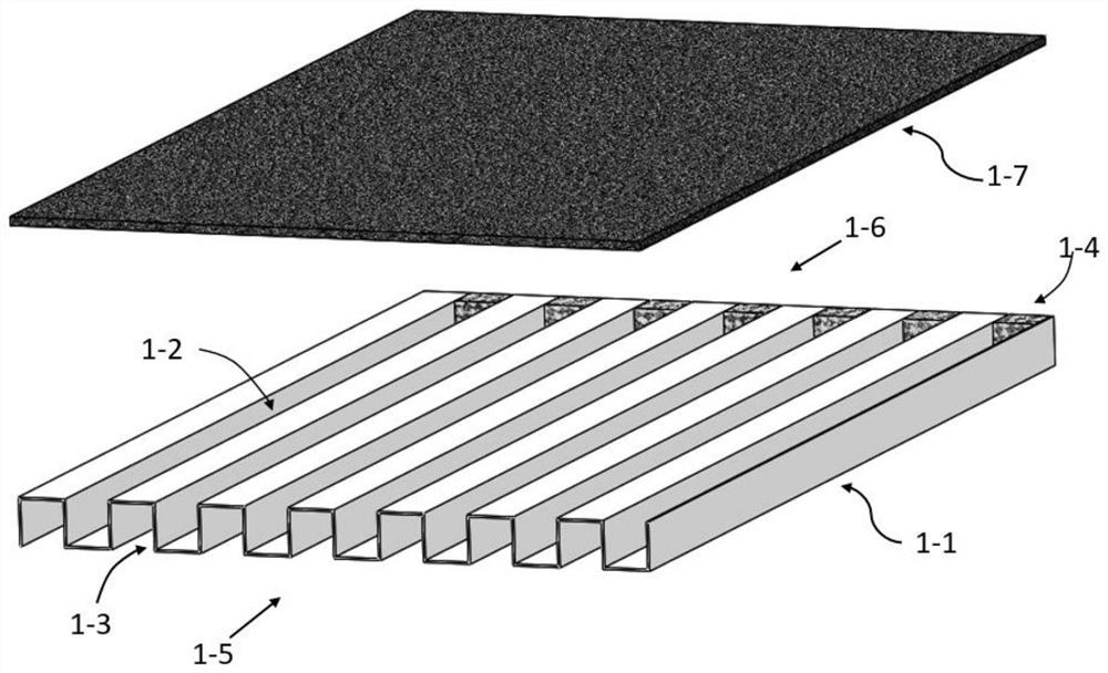
[0027] The following will refer to the appendix Figure 1 to Figure 3 Specific embodiments of the present invention are described in more detail. While specific embodiments of the present invention are shown in the drawings, it should be understood that the present invention may be embodied in various forms and should not be limited by the embodiments set forth herein. Rather, these embodiments are provided so that the present invention will be more thoroughly understood, and will fully convey the scope of the present invention to those skilled in the art.

[0028] It should be noted that certain terms are used in the description and claims to refer to specific components. It should be understood by those skilled in the art that the same component may be referred to by different nouns. The description and the claims do not use the difference in terms as a way to distinguish components, but use the difference in function of the components as a criterion for distinguishing. A...


PUM


Abstract

The invention discloses a cathode flow field plate structure of an air-cooled fuel cell and a fuel cell. In the cathode flow field plate structure, at least one gas channel introduces gas to provide reaction gas, and a membrane electrode covers the gas channel to contact the gas channel. The reaction gas introduced in the gas passage, at least one cooling passage introduces gas to cool and dissipate heat, the gas passage and the cooling passage are arranged alternately to form a groove-ridge structure, and the inlet sides of the gas passage and the cooling passage face the first direction to synchronize Gas is introduced, the exit side of the gas passage and the cooling passage faces a second direction opposite to the first direction, and the blocking unit is arranged on the exit side of the gas passage to block the reaction gas in the gas passage.

Description

technical field [0001] The invention belongs to the technical field of air-cooled fuel cells, in particular to a cathode flow field plate structure of an air-cooled fuel cell and an air-cooled fuel cell. Background technique [0002] Small mobile power devices, such as drones, automatic delivery machines, and park commuter vehicles, require long battery life and fast charging characteristics due to their nature of work. Traditional rechargeable batteries have low energy density and charging time is too long to meet this demand. Proton exchange membrane fuel cells have advantages in this field because of their higher energy density and faster gas charging speed, and can be used as an alternative energy source. In the proton exchange membrane fuel cell, compared with the traditional water-cooled battery, the air-cooled fuel cell reduces the circulation system such as the water pump, has a compact structure, a simple system, lighter weight, low cost and long battery life. It i...

Claims


Application Information

Patent Timeline
Patent Type & Authority Patents(China)
IPC IPC(8): H01M8/0267H01M8/04014H01M8/0258H01M8/1004
CPCH01M8/0267H01M8/04014H01M8/0258H01M8/1004Y02E60/50
Inventor 陈黎彭明张瑞元刘丽娜徐伟强陶文铨
Owner XI AN JIAOTONG UNIV
Why Eureka
Try Eureka