Environment light sensor and electronic equipment
An ambient light sensor and electronic device technology, applied in the field of electronics, can solve the problems of reduced detection accuracy of the ambient light sensor and the like
- Summary
- Abstract
- Description
- Claims
- Application Information
AI Technical Summary
Problems solved by technology
Method used
Image
Examples
Embodiment 1
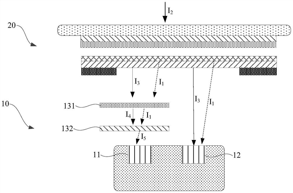
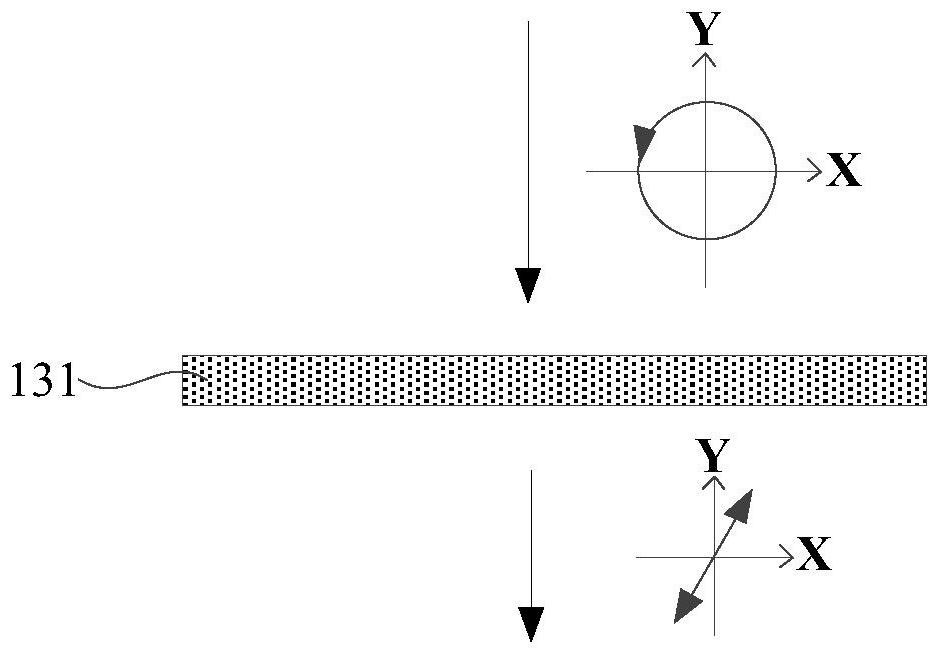
[0056] figure 1 It is a structural schematic diagram of an ambient light sensor provided in Embodiment 1 of the present application applied to electronic equipment, figure 2 It is a schematic diagram of the optical path of circularly polarized light passing through the first quarter-wave plate provided in Embodiment 1 of the present application.
[0057] An ambient light sensor 10 provided in an embodiment of the present application is applied to an electronic device 100, see figure 1 As shown, specifically, when the ambient light sensor 10 is applied to the electronic device 100 , the ambient light sensor 10 is disposed under the screen 20 of the electronic device 100 .
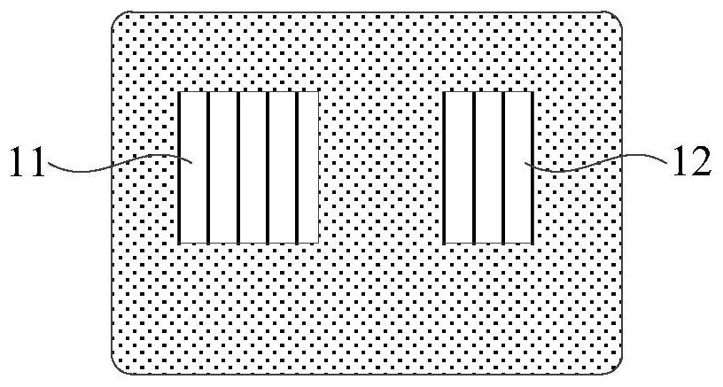
[0058] The ambient light sensor 10 includes a first receiving unit 11, a second receiving unit 12, a first linear polarizer 132 and a first quarter wave plate 131, wherein the first linear polarizer 132 is located on the first receiving unit 11 Above, the first quarter-wave plate 131 is located above the ...
Embodiment 2
[0090] Figure 7 It is a structural schematic diagram of an ambient light sensor provided in Embodiment 2 of the present application applied to electronic equipment.
[0091] see Figure 7 As shown, the difference from Embodiment 1 is that in the embodiment of the present application, the first quarter-wave plate 131 extends to the top of the second receiving unit 12, when the ambient light I 2 The ambient light I formed after passing through the screen 20 3 When it is irradiated onto the first quarter-wave plate 131, it can pass through the first quarter-wave plate 131 and then irradiates onto the second receiving unit 12, and the screen leaks 1 1 It can also be irradiated onto the second receiving unit 12 after passing through the first quarter-wave plate 131 .
[0092] The second receiving unit 12 is used to receive and detect the screen light leakage after passing through the first quarter wave plate 131, and the second receiving unit 12 is also used to receive and dete...
Embodiment 3
[0107] Figure 11 It is a structural schematic diagram of an ambient light sensor provided in Embodiment 3 of the present application applied to electronic equipment, Figure 12 It is a schematic diagram of the optical path of circularly polarized light after passing through the first linear polarizing plate provided in Embodiment 3 of the present application.
[0108] see Figure 11 As shown, the difference from Embodiment 1 is that in the embodiment of the present application, the first linear polarizing film 132 extends above the second receiving unit 12, and the first linear polarizing film 132 is also used to transmit light from the screen and the environment. Pass. That is, when ambient light I 2 The ambient light I formed after passing through the screen 20 3 When irradiating onto the first linear polarizing plate 132 , it can pass through the first linear polarizing plate 132 and then irradiate onto the second receiving unit 12 . Screen Light Leak I 1 It can also...
PUM
 Abstract
Description
Claims
Application Information
 - R&D Engineer
- R&D Manager
- IP Professional
- Industry Leading Data Capabilities
- Powerful AI technology
- Patent DNA Extraction
Browse by: Latest US Patents, China's latest patents, Technical Efficacy Thesaurus, Application Domain, Technology Topic, Popular Technical Reports.
© 2024 PatSnap. All rights reserved.Legal|Privacy policy|Modern Slavery Act Transparency Statement|Sitemap|About US| Contact US: help@patsnap.com


