
Inerter energy-consuming and efficiency-increasing device

A kind of inertial and No. 1 technology, applied in the field of inertial energy consumption and efficiency enhancement devices, can solve the problems of cylinder jacking, difficult processing, complicated mechanism, etc., and achieve the effect of controlling dynamic response, simple processing, and clear mechanism

Pending Publication Date: 2021-06-15
TONGJI UNIV
View PDF10 Cites 3 Cited by
  • Summary
  • Abstract
  • Description
  • Claims
  • Application Information

AI Technical Summary

Problems solved by technology

Some scholars have proposed an inertial mass damper consisting of two parts: a rotating viscous damping element and an inertial element. The cylinder of the viscous damping element and the ball nut in the inertial element rotate synchronously, thereby amplifying the mass and damping effect. This kind of inertial capacity energy consumption efficiency enhancing device has a complicated mechanism, is difficult to process, and is not easy to realize. It has not been popularized and used at present.
[0003] Some scholars proposed in the patent CN102494080A an integrated shock absorber device in which an inerter and a damper are connected in parallel. The pressure in the cylinder changes sharply. During the process of pulling out and retracting the guide rod, there will be a vacuum and top dead phenomenon in the oil cylinder, which hinders the movement of the guide rod, resulting in very unsatisfactory output and vibration damping performance, and cannot guarantee the stability of its axial force. Balanced, difficult to put into practical use
At the same time, since the flywheel in the shock absorber device is located in the inertial working chamber, the overall transverse width is relatively large, which meets the requirement that the shock absorber device is suitable for the field of automobile engineering. Considering the small space for the arrangement of the inerter and the limited working stroke of the inerter and the damper, the main purpose of integrating the inerter with the damper is to overcome the shortcomings of the small layout space and limited working stroke of the mechanical components in the vehicle chassis, and the damping structure part It uses the piston, piston rod and throttle valve to work together, which also makes the device short stroke and limited output. Therefore, the device has small tonnage, short stroke and limited output, which cannot solve the vibration control problem of large civil structures.

Method used


Image

  • Inerter energy-consuming and efficiency-increasing device
  • Inerter energy-consuming and efficiency-increasing device
  • Inerter energy-consuming and efficiency-increasing device

Examples


Embodiment

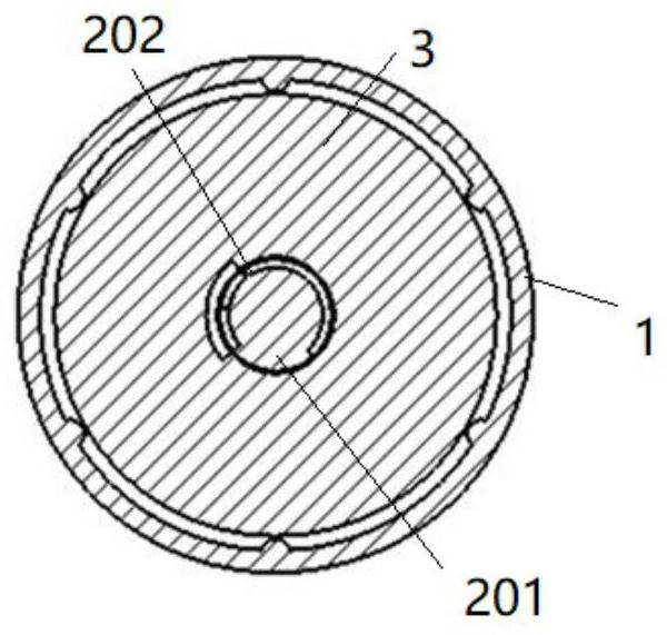
[0038] Such as figure 1 , 2 As shown in , 3, an inertia energy consumption synergistic device includes a ball screw inertial component and a viscous damping component, figure 2 The straight arrow in the direction of the ball screw inertial component in the figure points outward, indicating that the screw 201 moves axially outward, and the curved arrow indicates that the flywheel 3 is rotated by the movement of the screw 201. figure 2 The straight arrow in the direction of the viscous damping component points outward, indicating that the second outer cylinder 5 moves outward axially. At this time, the guide rod 6 moves axially in the opposite direction relative to the second outer cylinder 5, so that the piston 7 stirs Viscous fluid in the first chamber 501.

[0039] The ball screw inertial component includes No. 1 outer cylinder 1, a screw pair, a flywheel 3 and a flange 4. The No. 1 outer cylinder 1 is T-shaped, and the end with a larger outer diameter is used for setting...


PUM


Abstract

The invention relates to an inerter energy-consuming and efficiency-increasing device. The inerter energy-consuming and efficiency-increasing device comprises a ball screw type inerter assembly and a viscous damping assembly, wherein the ball screw type inerter assembly comprises a No. 1 outer cylinder, a screw pair and a rotating flywheel; a screw rod stroke chamber and a flywheel chamber communicated with the outside are arranged in the No. 1 outer cylinder; the screw pair comprises a screw rod, a nut and a plurality of balls; the viscous damping assembly comprises a No. 2 outer cylinder, a guide rod and a piston; the No. 2 outer cylinder is connected with the No. 1 outer cylinder; a main cavity and an auxiliary cavity which are communicated with each other are formed in the No. 2 outer cylinder; the main cavity is communicated with the screw rod stroke chamber; the guide rod is connected with the screw rod; the piston divides the main cavity into a No. 1 chamber and a No. 2 chamber; and the No. 1 chamber and the No. 2 chamber are both filled with viscous fluid. Compared with the prior art, the device is large in output force, long in stroke, capable of avoiding the dead jacking phenomenon and enhancing the stability through the double-outlet-rod structure, simple in form and easy to achieve; and the device is mounted in a structure after being connected with a spring or a support and the like, an asynchronous phase can be generated with the structure, and energy absorption-energy dissipation damping synergy is generated.

Description

technical field [0001] The invention belongs to the field of vibration control, and in particular relates to an inertia capacity energy consumption synergist. Background technique [0002] At present, inertial components are generally used as independent devices, connected with energy dissipation devices, springs, etc. to form a vibration damping system, and each component is individually designed and processed before being put into use. Some scholars have proposed an inertial mass damper consisting of two parts: a rotating viscous damping element and an inertial element. The cylinder of the viscous damping element and the ball nut in the inertial element rotate synchronously, thereby amplifying the mass and damping effect. This kind of inertial capacity energy consumption efficiency increasing device has a complex mechanism, is difficult to process, and is not easy to realize, so it has not been popularized and used at present. [0003] Some scholars proposed in the patent...

Claims


Application Information

Patent Timeline
IPC IPC(8): F16F9/30F16F9/504F16F15/30
CPCF16F9/303F16F9/504F16F15/30
Inventor 张瑞甫张璐琦
Owner TONGJI UNIV
Learn More