Short-limb steel plate shear wall with replaceable energy dissipation components and construction method thereof

A steel plate shear wall and shear wall technology, applied in building components, walls, building structures, etc., can solve the problems of large lateral stiffness, occupying land resources, and short natural vibration period.

Pending Publication Date: 2021-06-15
XIAN UNIV OF TECH
View PDF10 Cites 0 Cited by
  • Summary
  • Abstract
  • Description
  • Claims
  • Application Information

AI Technical Summary

Problems solved by technology

[0003] The current frame structure has significant node stress concentration and small lateral stiffness, which is a flexible structure. The frame structure has a large horizontal displacement under the action of strong earthquakes, which is likely to cause serious structural damage.
The current reinforced concrete shear wall structure has a large self-weight, large lateral stiffness, short natural vibration period of the structure, and poor ductility, which is not conducive to earthquake resistance.
In addition, due to the continuous acceleration of building renewal, a large number of old urban residential areas have been demolished, resulting in a huge amount of waste concrete, which seriously pollutes the ecological environment and occupies valuable land resources.

Method used


Image

  • Short-limb steel plate shear wall with replaceable energy dissipation components and construction method thereof
  • Short-limb steel plate shear wall with replaceable energy dissipation components and construction method thereof
  • Short-limb steel plate shear wall with replaceable energy dissipation components and construction method thereof

Examples


Embodiment Construction

[0037] The present invention will be further described in detail below in conjunction with specific embodiments, which are explanations of the present invention rather than limitations.

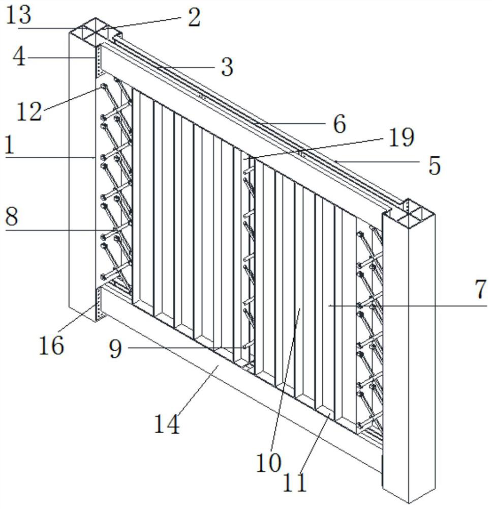
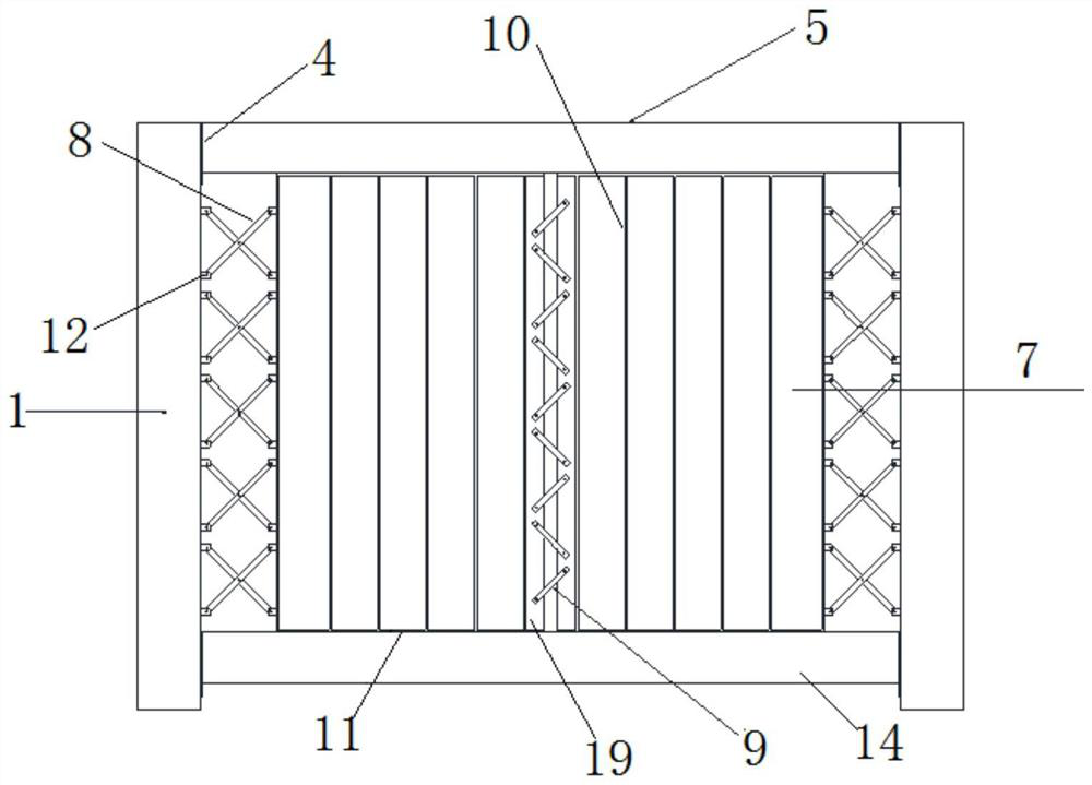
[0038] The present invention is a short-limb steel plate shear wall that can replace energy-dissipating components, such as figure 1 and figure 2 As shown, it includes a steel column 1, a first beam 5, a first connecting plate 8, a second connecting plate 9, a second beam 14 and a steel plate shear wall.

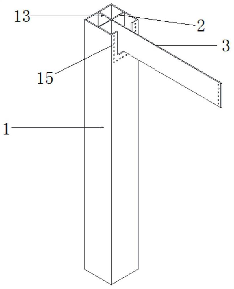
[0039] There are two steel columns 1, two steel columns 1 of the same length are arranged parallel and flush, and a first beam 5 and a second beam 14 are fixedly connected between the two steel columns 1, and the first beam 5 is higher than the second beam 14. Both ends of the first beam 5 and the second beam 14 are perpendicular to the two steel columns 1 .

[0040] Two steel plate shear walls are fixedly connected between the first beam 5 and the second beam 14, such as Figure 7 As s...


PUM


Abstract

The invention discloses a short-limb steel plate shear wall with replaceable energy dissipation components and a construction method thereof. A first cross beam and a second cross beam are fixed to a position between steel columns in the shear wall, shear wall bodies are to a position fixed between the first cross beam and the second cross beam, the supporting plates and the rib plates in each shear wall body are perpendicular to the lower end faces and the upper end faces of the cross beams, the two sides of the supporting plates make contact with the rib plates, the rib plates are perpendicular to the width direction of the supporting plates, gaps are reserved between the rib plates and the steel columns, the shear wall bodies are arranged at intervals, the centers of first connecting plates are in cross contact and then fixed to form a first energy dissipation component, the two ends are fixed between the steel columns and the rib plates, and the shear wall bodies are fixed through second connecting plates, the first cross beam, the supporting plates, the rib plates and the second cross beam are made of steel, and the first connecting plates and the second connecting plates are made of low-yield-point steel. During construction, after the steel columns are fixed as required, the first cross beam and the second cross beam are fixed to the position between the two steel columns, recycled concrete is poured into the steel columns and the cross beams, and subsequent installation is completed after the recycled concrete forms required strength.

Description

technical field [0001] The invention relates to the technical field of building structures, in particular to a short-leg steel plate shear wall with replaceable energy-consuming components and a construction method thereof. Background technique [0002] In recent years, with the rapid development of the construction industry, there are various forms of building structures, but there are some problems in the current building structures. [0003] The current frame structure has significant stress concentration at the nodes, low lateral stiffness, and is a flexible structure. Under strong earthquakes, the frame structure produces a large horizontal displacement, which is likely to cause serious structural damage. The current reinforced concrete shear wall structure has a large self-weight, high lateral stiffness, short natural vibration period of the structure, and poor ductility, which is not conducive to earthquake resistance. In addition, due to the continuous acceleration ...

Claims


Application Information

Patent Timeline
IPC IPC(8): E04B2/56E04B2/58E04B2/60E04B1/98E04H9/02
CPCE04B2/56E04B2/58E04B2/60E04B1/98E04H9/021Y02A30/00
Inventor 马辉张国恒白恒宇刘方达强佳琪刘喜洋
Owner XIAN UNIV OF TECH
Why Eureka
Try Eureka