A drum type chemical raw material screening device with speed regulating function
A screening device and drum-type technology, which is applied in the fields of filtration, chemical instruments and methods, solid separation, etc., can solve problems such as single function, inapplicability to screening of fluid chemical raw materials, and difficulty in realizing stepless speed regulation.
- Summary
- Abstract
- Description
- Claims
- Application Information
AI Technical Summary
Problems solved by technology
Method used
Image
Examples
Embodiment 1
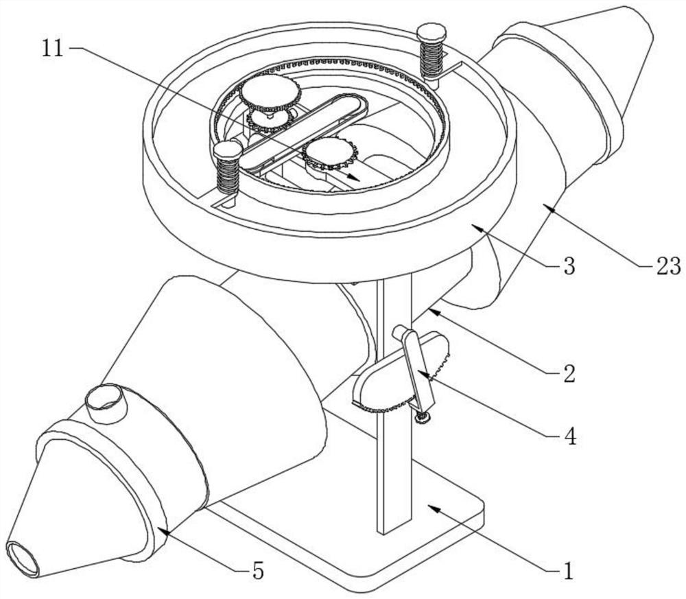
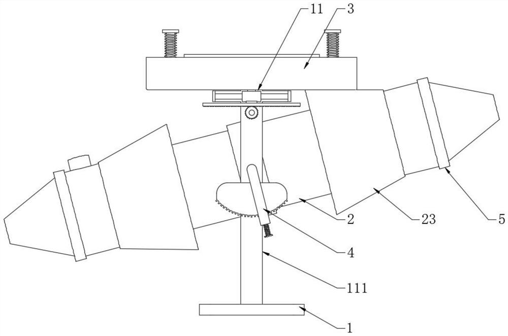
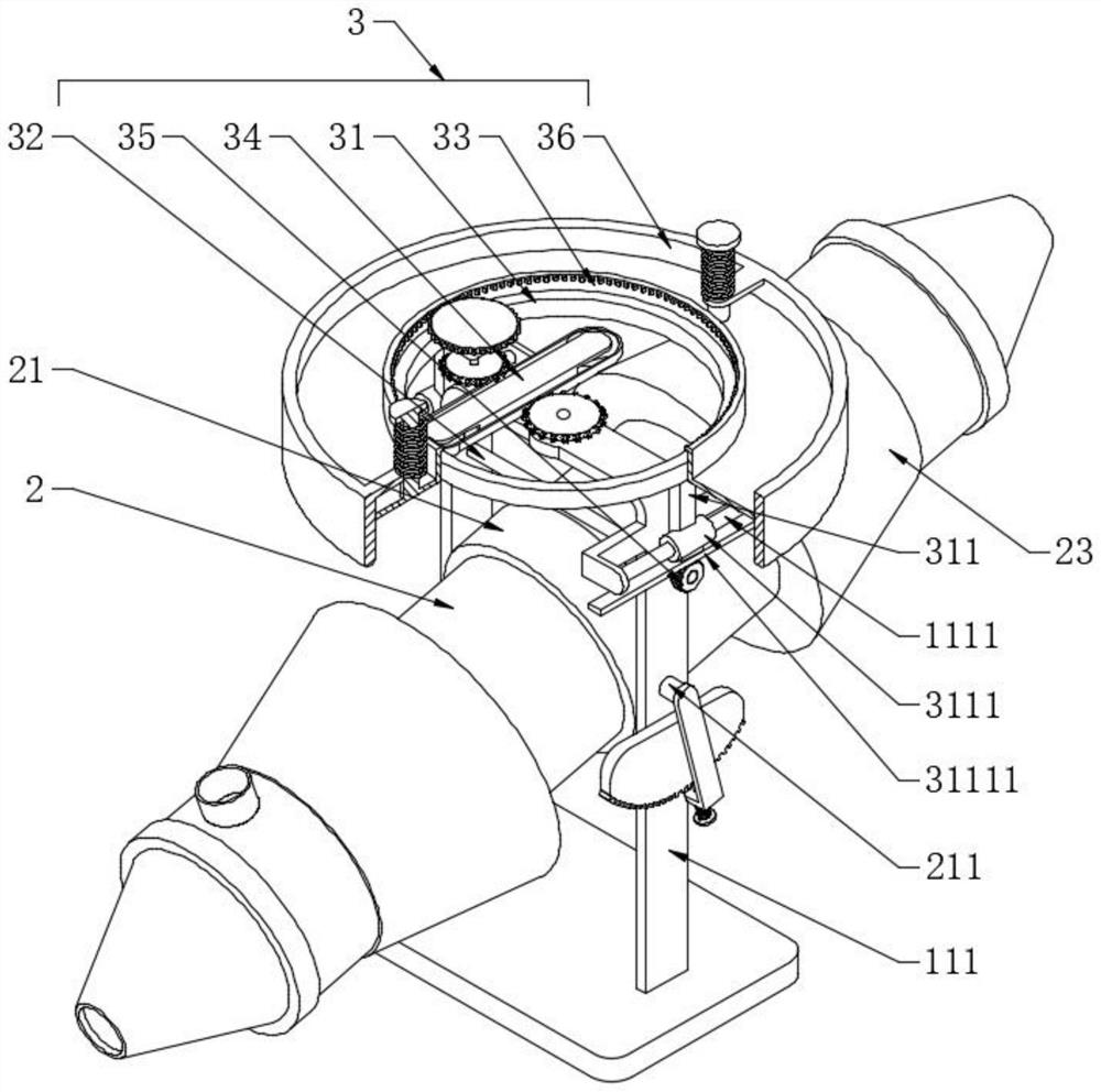
[0031] see Figure 1-3, a drum type chemical raw material screening device with speed regulation function, comprising a support frame 1, a cylinder 2 and a speed control combination 3, the upper end face of the support frame 1 is fixedly provided with a portal frame 11, and the cylinder 2 is set on the portal frame A rotating sleeve 21 is set inside and outside the frame 11, and the outer wall of the rotating sleeve 21 is fixedly provided with a supporting shaft 211 connected with the two vertical plates 111 on the portal frame 11. The cylinder 2 is distributed obliquely and has a height One end of the bottom is provided with a filter plate 1 22, and the speed regulating combination 3 is arranged on the top of the portal frame 11. The speed regulating combination 3 includes a supporting ring plate 31, an regulating shaft 32, a driving sleeve 33, a power combination 34, a driving gear 35 and a transmission Sleeve 36, the supporting annular plate 31 and the portal frame 11 are s...
Embodiment 2
[0033] see image 3 and Figure 4 , the difference from Embodiment 1 is that the transmission sleeve 36 and the driving sleeve 33 are axially elastically slidable, that is to say, the transmission sleeve 36 slides up and down relative to the driving sleeve 33. In this embodiment, it is possible to weld a For the annular disk, a vertical column is fixedly arranged on the upper end surface of the annular disk, and then a supporting plate with a matching hole is arranged on the top of the transmission sleeve 36. Sliding connection, the support shaft 211 and the vertical plate 111 are connected in rotation, so that the cylinder 2 can be controlled to swing with the support shaft 211 as the rotation center to change the inclination angle. One end of the support shaft 211 passes through the vertical plate 111 and is fixedly connected to the limit rod 4. One side of the vertical plate 111 is fixedly provided with a locking plate 1112 that cooperates with the limit rod 4. The limit r...
Embodiment 3
[0035] see Figure 4 , and the difference from Example 2 is that both ends of the cylinder 2 are provided with a cover 5, one side of the cover 5 is fixedly provided with a conical discharge pipe 51, and the outer wall of the cylinder 2 is located between the conical sleeve 23 and the seal. A feeding pipe 25 is arranged between the covers 5, and the feeding pipe 25 adopts a block structure. The cover 5 and the cylinder 2 are screwed together. The second filter plate 24 and the first filter plate 22 can be easily disassembled by removing the cover 5, and can also be replaced with different specifications, which is convenient for replacement.
[0036] Working principle: when in use, the drive shaft 344 is controlled to rotate, the drive sprocket 341 rotates to drive the chain 3433 to run, the chain 3433 drives the drive sprocket 3422 to rotate, and then the drive gear 3421 rotates and drives the drive sleeve 33 to rotate (opened on the inner peripheral wall of the drive sleeve 3...
PUM
 Abstract
Description
Claims
Application Information
 - R&D
- Intellectual Property
- Life Sciences
- Materials
- Tech Scout
- Unparalleled Data Quality
- Higher Quality Content
- 60% Fewer Hallucinations
Browse by: Latest US Patents, China's latest patents, Technical Efficacy Thesaurus, Application Domain, Technology Topic, Popular Technical Reports.
© 2025 PatSnap. All rights reserved.Legal|Privacy policy|Modern Slavery Act Transparency Statement|Sitemap|About US| Contact US: help@patsnap.com


