


Quick Research
Generate reliable direction feasibility study reports for your R&D in just a few steps.

Technical Q&A
Discover and master advanced knowledge NOW. Basics, ideas, possibilities, all at once.

Find Solutions
As an expert in R&D theories, this can generate solutions to your technical problems instantly.

Evaluate Feasibility
Analyze your overall solution with one click, know your potential R&D risks in advance.

Monitor Landscape
Get weekly tech updates, stay abreast of the latest tech innovations and key insights.
Camera optical axis correction device and method for multiple optical components
A technology of optical components and correction devices, which is applied to parts of color TVs, parts of TV systems, electrical components, etc., to achieve the effect of convenient operation, ensure the accuracy of calibration, and improve the efficiency and accuracy of calibration
- Summary
- Abstract
- Description
- Claims
- Application Information
AI Technical Summary
Problems solved by technology
Method used
Image

Examples
Embodiment 1
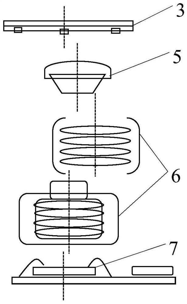
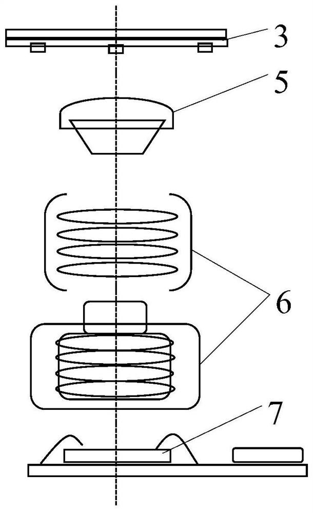
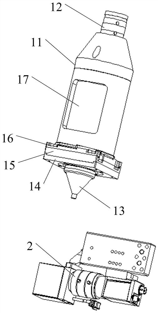
[0050] Example 1: By adjusting the reference Mark point portion 13 while observing, to realize that the central axis A2 of the reference Mark point portion 13 is on the same central optical axis as the center of field of view of the top vision camera 12, the following steps are included:
[0051] S11: Find the Mark point in the center of the Chart through the top vision camera 12, so that the center of view of the top vision camera 12 is consistent with the Chart image 3 The center Mark point coincides;
[0052] S12: Take the central axis A2 of the reference Mark point 13 as the rotation axis, rotate the optical axis calibration jig 1 around the rotation axis in the horizontal direction, and take a picture of the Chart through the top vision camera 12 image 3 Center Mark point imaging, if the field of view center of the top vision camera 12 and Chart image 3 If the central Mark point coincides, it indicates that the central axis A1 where the top vision camera 12 is locat...
Embodiment 2
[0054] Example 2: Adjust the top vision camera 12 by calculating the offset, so that the central axis A2 of the reference mark point 13 is on the same central optical axis as the center of view of the top vision camera 12, including the following steps:
[0055] S11: Taking the central axis A2 of the reference Mark point 13 as the rotation axis, rotate the optical axis calibration jig 1 in turn around the rotation axis in the horizontal direction by angle θ1, angle θ2, and angle θ3, and place the optical axis calibration jig 1 at an angle Shoot Chart at θ1, angle (θ1+θ2), and angle (θ1+θ2+θ3) positions image 3 The central Mark point imaging of the top vision camera 12, the central axis A1 where the center of the field of view of the top vision camera 12, the central axis A2 of the reference Mark point part 13, Chart image 3 The central axis A3 where the central Mark point is located is projected to the same horizontal plane as shown in the image Figure 6 shown;
[0056]...
PUM
 Abstract
Description
Claims
Application Information
 - R&D Engineer
- R&D Manager
- IP Professional
- Industry Leading Data Capabilities
- Powerful AI technology
- Patent DNA Extraction
Browse by: Latest US Patents, China's latest patents, Technical Efficacy Thesaurus, Application Domain, Technology Topic, Popular Technical Reports.
© 2024 PatSnap. All rights reserved.Legal|Privacy policy|Modern Slavery Act Transparency Statement|Sitemap|About US| Contact US: help@patsnap.com