
Steam generator

A technology of steam generator and steam cover, which is applied in steam generation, steam generation method, steam boiler, etc., can solve the problems of not being able to fully cover the heating plate, not being able to absorb heat energy well, and not being able to absorb heat energy, etc., so as to improve poor gasification. , to avoid the effect of water spray phenomenon

Pending Publication Date: 2021-06-11
佛山市顺德区飞湃科技有限公司
View PDF1 Cites 0 Cited by
  • Summary
  • Abstract
  • Description
  • Claims
  • Application Information

AI Technical Summary

Problems solved by technology

[0002] The existing steam generator is composed of a main body and an upper cover, such as a steam generator disclosed in the patent publication number CN205807373U, the heating element is arranged on the main body, and the steam chamber is also arranged on the main body, only the steam generator in the steam generator The main body generates heat. When the bottom surface of the main body of the steam generator is inclined to the horizontal plane during use, the water in the steam generator cannot fully cover the heating sheet provided in the main body, and it cannot absorb heat well, turning hydration into Gas, especially when the main body of the steam generator is turned upside down, the water in the steam generating element cannot touch the heating sheet provided in the main body, and it cannot absorb heat energy, and the water will be turned into gas, which is prone to gasification It can be seen that how to provide a steam generator that can effectively vaporize steam when the main body in the steam generating element is inclined to the horizontal plane is a technical problem that those skilled in the art need to solve urgently

Method used


Image

  • Steam generator
  • Steam generator
  • Steam generator

Examples


Embodiment Construction

[0025] In order to more clearly illustrate the embodiments of the present invention or the technical solutions in the prior art, the present invention will be further introduced below in conjunction with specific embodiments and accompanying drawings. Obviously, the accompanying drawings in the following description are only some embodiments of the present invention , for those skilled in the art, other drawings can also be obtained according to these drawings on the premise of not paying creative work.

[0026] It should be understood that the orientation or positional relationship indicated by the terms "upper", "lower", "front", "rear", "left", "right", "horizontal", "top", "inner" etc. are based on The orientation or positional relationship shown in the drawings is only for the convenience of describing the present invention and simplifying the description, and does not indicate or imply that the referred device or element must have a specific orientation, be constructed an...


PUM


Abstract

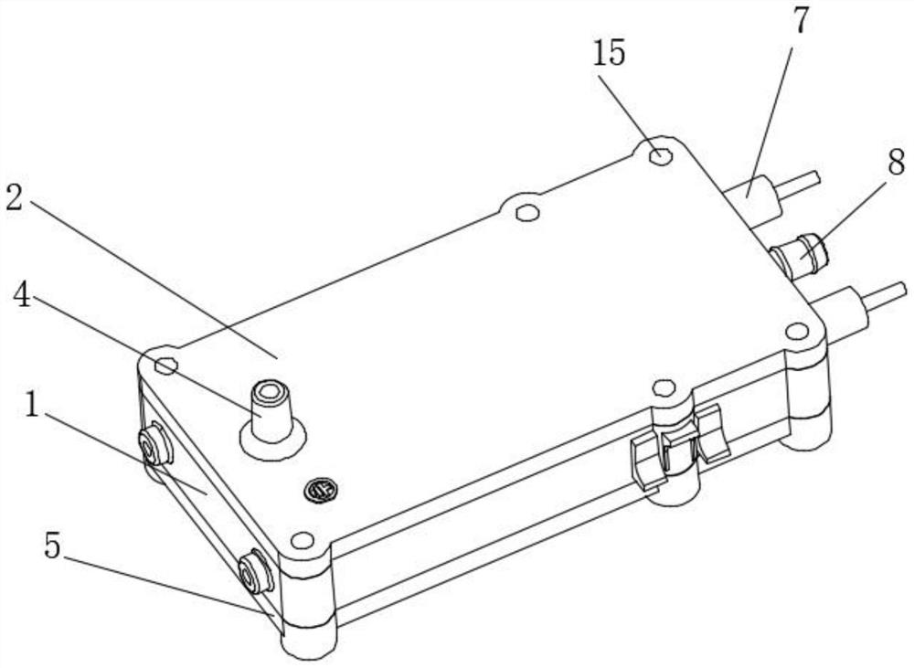
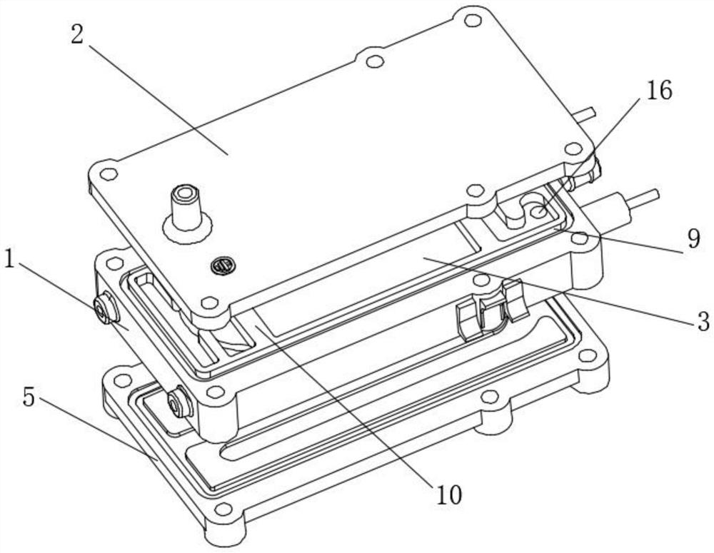
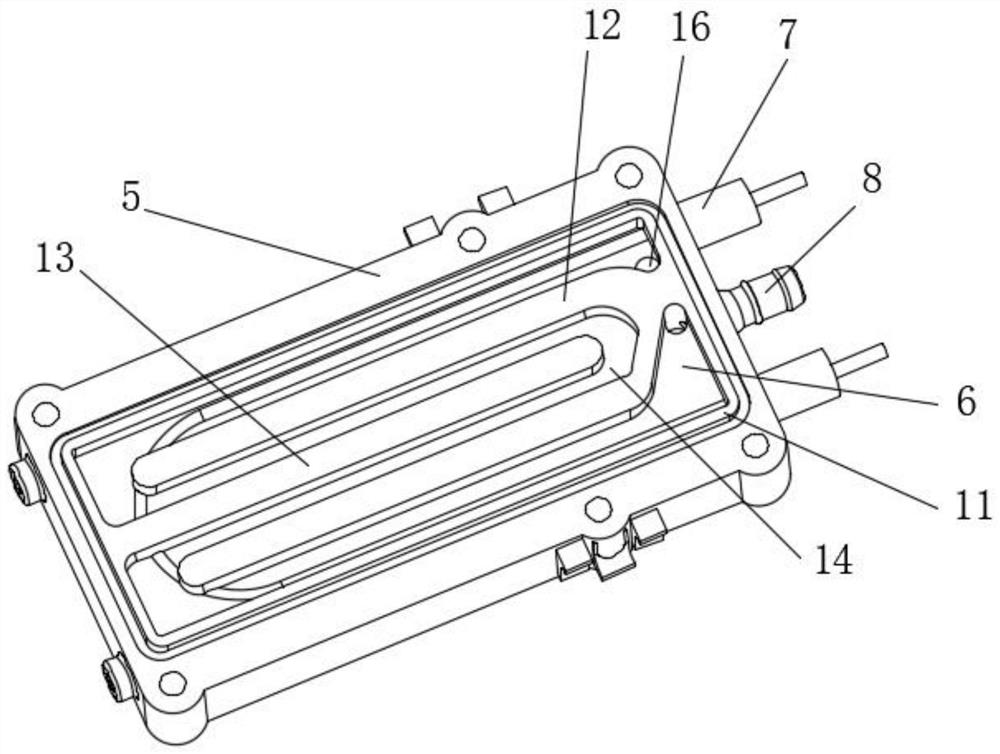
The invention relates to a steam generator which comprises a heating core. A water inlet cover is arranged at the top end of the heating core, a first water containing cavity is formed in the top end of the heating core, a first gasification chamber is defined by the water inlet cover and the first water containing cavity, a steam cover is arranged at the bottom end of the heating core, a second water containing cavity is formed in the bottom end of the heating core, a second gasification chamber is defined by the steam cover and the second water containing cavity, and the first gasification chamber is communicated with the second gasification chamber; a heating element is arranged in the heating core, the heating element can heat water entering the first water containing cavity and the second water containing cavity to vaporize the water, and when a main body in a steam generating element and the horizontal plane form an inclined angle, even when the main body faces upwards and is in an inverted state, the first gasification chamber performs first gasification, and the second gasification chamber performs second gasification on water drops which are poor in gasification in the first gasification chamber, so that poor gasification is improved, and the water spraying phenomenon is avoided.

Description

technical field [0001] The invention relates to the technical field of steam generating equipment for household appliances, in particular to a steam generator. Background technique [0002] The existing steam generator is composed of a main body and an upper cover, such as a steam generator disclosed in the patent publication number CN205807373U, the heating element is arranged on the main body, and the steam chamber is also arranged on the main body, only the steam generator in the steam generator The main body generates heat. When the bottom surface of the main body of the steam generator is inclined to the horizontal plane during use, the water in the steam generator cannot fully cover the heating sheet provided in the main body, and it cannot absorb heat well, turning hydration into Gas, especially when the main body of the steam generator is turned upside down, the water in the steam generating element cannot touch the heating sheet provided in the main body, and it can...

Claims


Application Information

Patent Timeline
IPC IPC(8): F22B1/28F22B37/02F22B37/22
CPCF22B1/28F22B37/02F22B37/22
Inventor 蔡自光周国辉陈振华劳锟沂
Owner 佛山市顺德区飞湃科技有限公司
Learn More