
A watch clamp with self-locking device

A technology of self-locking device and meter clamping device, which is applied in the direction of measuring device, testing/calibrating device, instrument, etc., and can solve problems such as damage to operators or equipment, water spraying of the device, and wear of the sealing ring 1, so as to reduce uncertainty factors, reduce human control, and maintain the effect of stability

Active Publication Date: 2018-06-19
HANGZHOU ZHONGPEI ELECTRONICS
View PDF9 Cites 0 Cited by
  • Summary
  • Abstract
  • Description
  • Claims
  • Application Information

AI Technical Summary

Problems solved by technology

[0003] 1. During the normal operation of the detection device, the operator unconsciously touches the switch stem of the three-position four-way valve, and high-pressure water in the pipeline will spray out, causing damage to the operator or equipment, and a large amount of water in the workplace will affect normal operations. In production work, if the measured medium in the pipeline is high-temperature water, the damage to the body will be greater
[0004] 2. Due to the lack of experience of the operator, or forgetting to open the watch clamp, starting to operate the equipment will also cause the problem of water spraying of the device, so directly using the hand-turned three-position four-way valve to control the actuator has a great potential safety hazard. Higher requirements for personnel
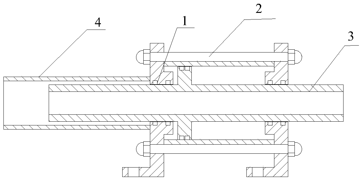
However, the long-term friction between the outer casing 2 and the piston 3 will cause the wear of the sealing ring 1. When the air pressure is 0.6Mpa, the gas will be squeezed to the liquid pipeline 4 through the sealing ring, causing a safety hazard

Method used


Image

  • A watch clamp with self-locking device
  • A watch clamp with self-locking device
  • A watch clamp with self-locking device

Examples


Embodiment 1

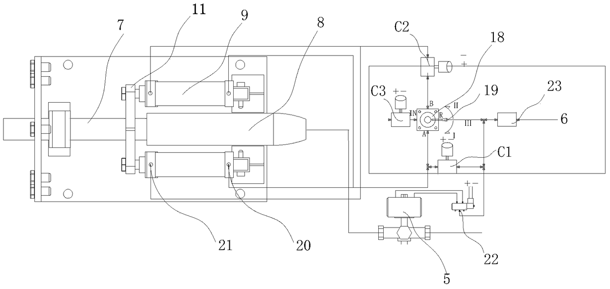
[0039] A watch clip with a self-locking device, which includes a control structure and a watch clip main body. The control structure includes a main water inlet valve 5, a main air intake pipe 6, a reversing valve and a power supply module. The main body of the meter clamp includes a water inlet pipe 7, a casing 8 installed outside the water inlet pipe, and a cylinder connected to the water inlet pipe. There are two O-shaped sealing rings inside the front end of the casing, and a part of the water inlet pipe extends into the casing. Through the O-shaped The sealing ring is sealingly connected with the sleeve pipe.

[0040] This cylinder is external double cylinder 9, is respectively positioned at the left and right sides outside water inlet pipe and sleeve pipe, and two pistons of external double cylinder are connected by a horizontal push plate 11, and are fixed on the outside of water inlet.

[0041] The outside of the main body of the watch clamp is provided with a watch cl...

Embodiment 2

[0060] In the structure in embodiment 1, add two delay control switches, be respectively open delay switch and close delay switch;

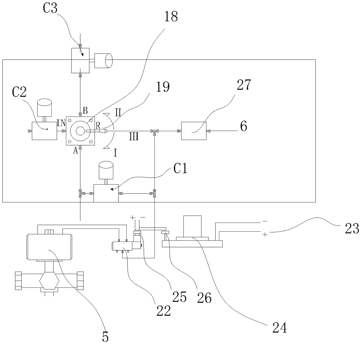
[0061] The power supply module includes a power supply 23 and a relay 24, and the two-position two-way solenoid valve C1, the two-position two-way solenoid valve C2 and the two-position two-way solenoid valve C3 are all controlled by the relay. The opening delay switch 25 and the closing delay switch 26 are connected to the power supply, and the opening delay switch 25 is connected to the two-position five-way solenoid valve 22, that is, the two-position five-way solenoid valve 22 is connected to the power supply 23 through the opening delay switch 25. The off-delay switch is connected to the relay 24, and the relay 24 is connected to the power supply.

[0062] The control method of the watch holder with two time-delay control switches includes the following steps:

[0063] Verification starts:

[0064] 1. Switch the valve stem to the valve ste...


PUM


Abstract

A watch clip with a self-locking device, which includes a control structure and a watch clip main body, the control structure includes a three-way four-position valve, a main water inlet valve, a closing delay switch and an opening delay switch, the three-way four-position The working port A port and B port of the position valve and the port connected to the atmospheric end are respectively connected with switch one, switch two and switch three, and the other end of the switch one is connected with the main air intake pipe, and the main air intake pipe is also connected with a switch Fourth, the air inlet, switch one, and switch four are connected in parallel, and the switch four is connected to the main water inlet cut-off valve. Wherein, the relay connected to the power supply controls the first switch, the second switch and the third switch, the on-delay switch and the off-delay switch are connected to the power supply, the on-delay switch is connected to the switch four, and the off-delay switch is connected to the main switch. The above-mentioned structure improves the safety performance of the watch holder during operation, and prevents potential safety hazards caused by human error in operation.

Description

technical field [0001] The invention relates to the field of factory inspection of water meters, in particular to a meter holder of a water meter inspection device. technical background [0002] At present, the meter holders of the water meter calibration station on the market do not have the self-locking function, and basically use the three-position four-way hand valve to directly control the actuator. In the actual use process, there will be the following problems: [0003] 1. During the normal operation of the detection device, the operator unconsciously touches the switch stem of the three-position four-way valve, and high-pressure water in the pipeline will spray out, causing damage to the operator or equipment, and a large amount of water in the workplace will affect normal operations. In production work, if the measured medium in the pipeline is high-temperature water, the personal injury will be greater. [0004] 2. Due to the lack of experience of the operator, or...

Claims


Application Information

Patent Timeline
Patent Type & Authority Patents(China)
IPC IPC(8): G01F25/00
Inventor 闻春利陈冰根杨起
Owner HANGZHOU ZHONGPEI ELECTRONICS
Learn More