
Split type electric control silicone oil clutch water pump

A silicone oil clutch, split-type technology, applied in the direction of clutches, magnetic drive clutches, non-mechanical drive clutches, etc., can solve the problems of increased clutch coupling and separation response time, impeller failure, and increased product scrap rate, etc., to achieve improved responsiveness , reduce the risk of sticking, and improve the effect of assembly methods

Pending Publication Date: 2021-06-11
SUZHOU RISING AUTO PARTS
View PDF1 Cites 2 Cited by
  • Summary
  • Abstract
  • Description
  • Claims
  • Application Information

AI Technical Summary

Problems solved by technology

The assembly process is cumbersome and the working hours are lengthy; 2. Product performance: the active part and the driven part are connected by bearings. In the case of damage to the bearing due to excessive load, the coupling and separation response time of the clutch will be greatly increased
The heat dissipation of the internal combustion engine driven by the water pump is a heat exchange. The heat in the cylinder must be quickly transferred to the cooling liquid. The specific heat capacity of the cooling liquid is large. The cooling performance of the internal combustion engine is greatly reduced by reducing the warm-up time and reducing harmful emissions during the start-up phase. It is very important that the clutch needs to respond quickly and have high consistency. If the clutch cannot be quickly separated from the coupling, the impeller will not work normally; 3. Cost: In addition to increasing the assembly cost of the current technical structure of the electronically controlled silicon oil clutch water pump, the water pump The structure is also more cumbersome
For example, in the water pump structure described in CN 110966078 B "Internal Combustion Engine Mechanical Water Pump Electronically Controlled Silicone Oil Clutch", bearings are needed to support the rotation between the driving and driven parts, and the cost of components increases significantly; Finally, each component is tightly connected by pressure riveting. If there is a quality problem during product testing or loading, it will be difficult to disassemble and repair. This will greatly increase the product scrap rate and increase the cost of later maintenance and repair.

Method used


Image

  • Split type electric control silicone oil clutch water pump
  • Split type electric control silicone oil clutch water pump
  • Split type electric control silicone oil clutch water pump

Examples


Embodiment

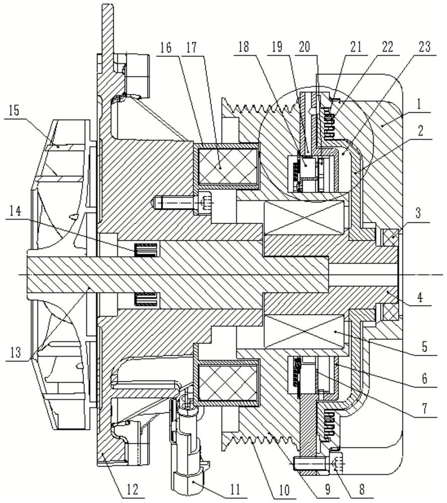
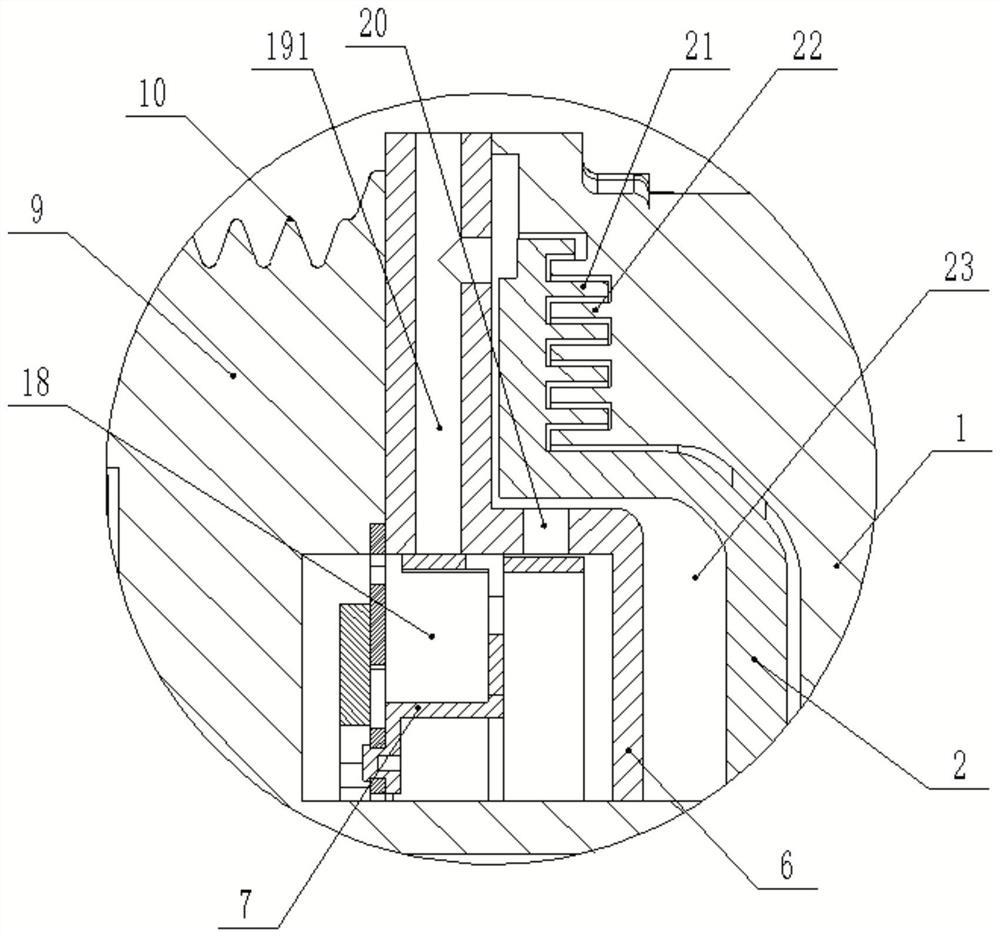
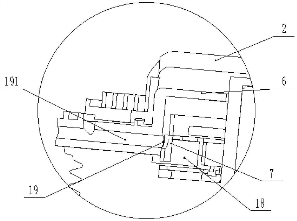
[0036] When the temperature of the engine increases or decreases, the signal sent by the temperature sensor on the engine is collected by the automobile ECU, and the automobile ECU transmits the temperature signal to the electronic control system of the electric water pump clutch. The control system control coil 17 is energized to control the switching action of the valve plate assembly 7. like figure 2 , image 3As shown, when the oil outlet 20 is opened, the oil return port 19 is closed by the valve plate assembly 7. When the belt pulley 9 connected with the engine gear train rotates, relying on the centrifugal force, the silicone oil in the oil storage chamber 18 is released from the oil outlet. The mouth 20 enters, passes through the engagement of the tooth groove 21 of the driven plate and the tooth groove 22 of the upper cover, and enters the working chamber 23. The tooth groove 21 of the driven plate interacts with the tooth groove 22 of the upper cover, and the drive...


PUM


Abstract

The invention discloses a split type electric control silicone oil clutch water pump, wherein a clutch part is rigidly connected with and fixed to a shaft connecting bearing of a water pump part through a driven shaft, the clutch water pump aims to change an original stacking type assembly manner, the risk of clamping stagnation of a driving part and a driven part is reduced, separation coupling response time can be optimized, the speed of an impeller is corrected more accurately, engine oil consumption is better reduced, the requirement of an engine cooling system is met, and the service life of parts of the cooling system is prolonged.

Description

technical field [0001] The invention relates to the field of cooling systems, in particular to a split type electronically controlled silicon oil clutch water pump. Background technique [0002] With the continuous application and promotion of the current electronically controlled silicon oil clutch water pump, customers continue to pay attention to the product performance of the electronically controlled silicon oil clutch water pump, only to prolong the service life of the electronically controlled silicon oil clutch water pump and improve the product performance of the electronically controlled silicon oil clutch water pump. [0003] As the structure of the current electronically controlled silicon oil clutch water pump adopts the active part to provide the power source, which drives the driven part to rotate, so as to realize the working mode of the water pump impeller, the bearing between the active part and the driven part is used to provide rotational support to ensure...

Claims


Application Information

Patent Timeline
Patent Type & Authority Applications(China)
IPC IPC(8): F01P5/12F01P7/14F01P11/00F04D15/00F04D29/00F04D29/044F04D29/62F16D27/14
CPCF01P5/12F01P7/14F01P11/00F04D15/00F04D29/007F04D29/044F04D29/628F16D27/14
Inventor 沈玉枫刘敦绿岳胜桥宋大凯吴海峰尚云飞
Owner SUZHOU RISING AUTO PARTS
Learn More