Electro-hydraulic servo braking system with pedal simulator
A pedal simulator, braking system technology, applied in the direction of brake safety system, brake, brake transmission, etc. Satisfy the driver and other problems, and achieve the effect of shortening the braking distance, ensuring safety, and increasing the braking pressure
- Summary
- Abstract
- Description
- Claims
- Application Information
AI Technical Summary
Problems solved by technology
Method used
Image
Examples
Embodiment 1
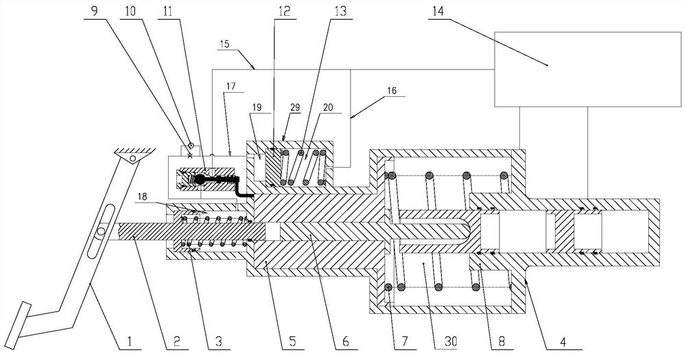
[0049] As shown in the figure, an electro-hydraulic servo braking system with a pedal simulator of the present invention includes:
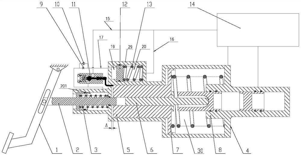
[0050] Housing 4, the inside of which is formed with push rod piston cavity 18, cavity 30 and simulator cavity 29;
[0051] The brake pedal 1 is installed on the left side of the housing 4;
[0052] The push mechanism driven by the brake pedal 1 includes a pedal push rod 2 and an electric control push rod 5. The pedal push rod 2 is slidably installed in the push rod piston chamber 18, and the left end of the pedal push rod 2 is connected to the brake pedal. 1 connection, the right end extends into the electric control push rod 5, the electric control push rod 5 is slidably installed in the cavity 30, and a gap is formed between the pedal push rod 2 and the electric control push rod 5;
[0053] The brake mechanism driven by the push mechanism to achieve braking includes a master cylinder jack 6 and a brake master cylinder 8. The left end of the m...
Embodiment 2
[0071] On the basis of Embodiment 1, the electro-hydraulic servo braking system further includes:
[0072] The pedal displacement sensor is used to obtain the displacement signal of the driver stepping on the brake pedal 1;
[0073] The electronic control unit is used to calculate the total braking force required for this braking according to the pedal displacement signal, and then calculate the braking force required by the electro-hydraulic servo braking system according to the state of the motor and battery, and control the electronically controlled push rod through the motor 5 run.
[0074] After the driver steps on the brake pedal 1, the pedal displacement displacement sensor obtains the displacement signal of the brake pedal 1, and sends a running command and the motion stroke of the electric control push rod 5 to the electric control push rod 5 through the electronic control unit to judge the The displacement of the piston of the brake master cylinder 8 of the hydrauli...
Embodiment 3
[0077] On the basis of Embodiment 2, an annular piston is installed on the side of the pedal push rod 2 close to the push rod return spring 3 .
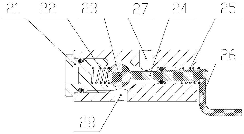
[0078] Furthermore, the hydraulic valve plug 21 is screwed into the hydraulic valve 11 .
PUM
 Abstract
Description
Claims
Application Information
 - R&D
- Intellectual Property
- Life Sciences
- Materials
- Tech Scout
- Unparalleled Data Quality
- Higher Quality Content
- 60% Fewer Hallucinations
Browse by: Latest US Patents, China's latest patents, Technical Efficacy Thesaurus, Application Domain, Technology Topic, Popular Technical Reports.
© 2025 PatSnap. All rights reserved.Legal|Privacy policy|Modern Slavery Act Transparency Statement|Sitemap|About US| Contact US: help@patsnap.com


