Broadband high-efficiency transmission type polarization converter

A high-efficiency, transmissive technology, applied in the direction of electrical components, antennas, etc., can solve the problems of high loss and cost, complex structure of electric polarization converter, etc., achieve enhanced angle stability, improve polarization and angle stability , Design simple and flexible effects

Inactive Publication Date: 2021-06-08
中国人民解放军91206部队
View PDF6 Cites 1 Cited by
  • Summary
  • Abstract
  • Description
  • Claims
  • Application Information

AI Technical Summary

Problems solved by technology

[0006] The purpose of the present invention is to address the above-mentioned deficiencies in the prior art, and to provide a polarization converter based on a multilayer frequency selective surface, which can solve the problem of complex structure and loss of electrical control polarization converter while ensuring high performance. and high cost

Method used


Image

  • Broadband high-efficiency transmission type polarization converter
  • Broadband high-efficiency transmission type polarization converter
  • Broadband high-efficiency transmission type polarization converter

Examples


Embodiment 1

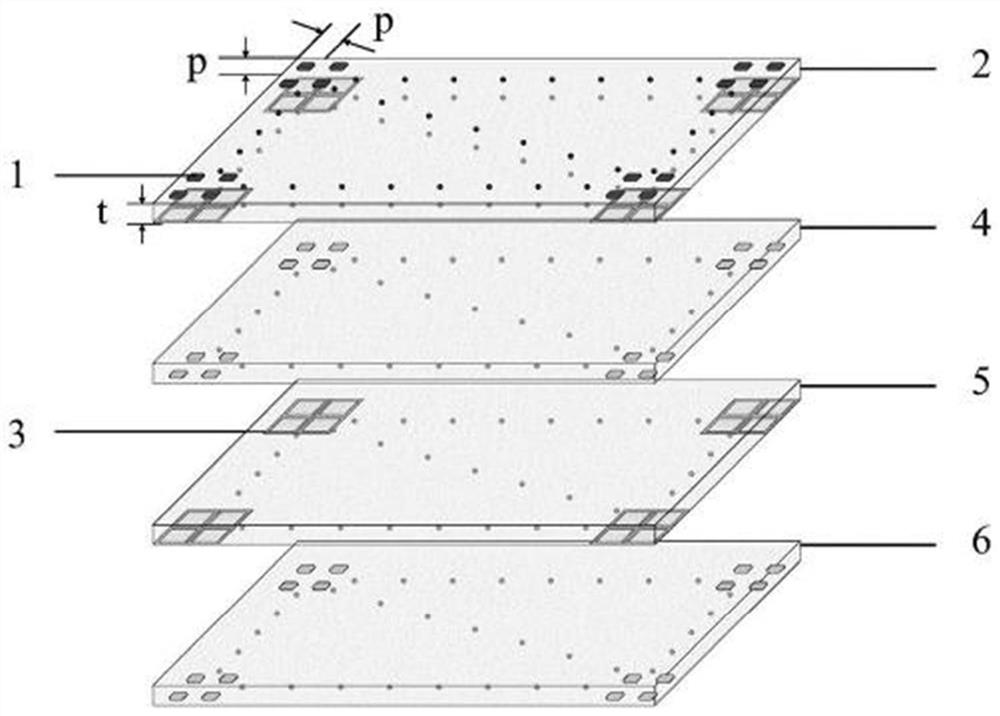
[0029] refer to figure 1 , the first dielectric plate 2, the second dielectric plate 4, the third dielectric plate 5 and the fourth dielectric plate 6 are all made of polytetrafluoroethylene material, the relative permittivity εr=2.6±0.05, the dielectric loss tanδ=0.015, The thickness of the substrate is t=1.5mm; on the upper surface of the first dielectric board 2, the lower surface of the second dielectric board 4 and the lower surface of the fourth dielectric board 6 are respectively printed with 8×8 corner-cut square patches 11 The patch array 1 composed of the first dielectric plate 2 and the lower surface of the third dielectric plate 5 are respectively printed with a grid array 3 composed of 8×8 metal square rings 33; the first dielectric plate 2, The second dielectric plate 4 , the third dielectric plate 5 and the fourth dielectric plate 6 are sequentially fixed from top to bottom by hot pressing with insulating adhesive materials or using dielectric screws to form an ...

Embodiment 2

[0033] The structure of embodiment 2 is the same as that of embodiment 1, and only the following parameters are adjusted:

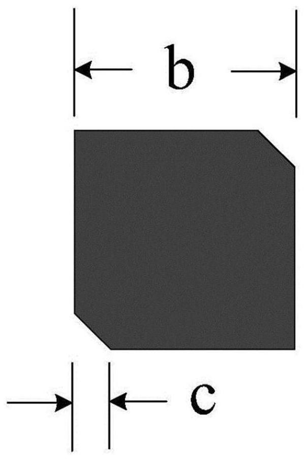
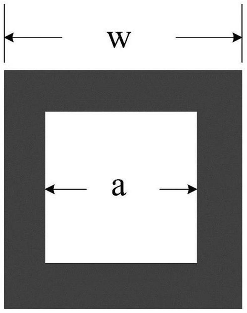
[0034] The four-layer dielectric plates 2, 4, 5 and 6 are all made of Teflon(tm), whose relative permittivity εr=2.1, dielectric loss tanδ=0.001, and substrate thickness t=1mm; The number of periodic elements of the array 3 is M×N=2×2, and the period p=8mm; the length of the square patch 11 is b=5mm, the length of the chamfered side is c=1.5mm; the length of the outer side of the square ring 33 is w=8mm, the length of the inner side a=6mm.

Embodiment 3

[0036] The structure of embodiment 3 is the same as that of embodiment 1, and only the following parameters are adjusted:

[0037] The four-layer dielectric plates 2, 4, 5, and 6 all use TaconicCER-10(tm), whose relative permittivity εr=10, dielectric loss tanδ=0.035, and substrate thickness t=3mm; The number of periodic elements of the grid array 3 is M×N=128×128, the period p=20mm; the side length of the square patch 11 is b=15mm, and the chamfered side length is c=5mm; the outer side length of the square ring 33 is w=20mm, the inner side Length a=16mm.

[0038] The effect of the present invention is further described below in conjunction with the simulation results:

[0039] 1. Simulation content: using AnsysHFSS13.0, for example Figure 4The simulation model of the shown embodiment 1 carries out a full-wave simulation. In the frequency band range of 8.5GHz-11GHz, a standard gain horn is used as a transmission source, and a linearly polarized wave is emitted to vertically...


PUM


Abstract

The invention provides a broadband high-efficiency transmission type polarization converter. The converter is used for solving the problems of complex structure and high loss of an electrically tunable polarization converter. The upper surface of a first dielectric plate (2), the lower surface of a second dielectric plate (4) and the lower surface of a fourth dielectric plate (6) are respectively printed with a patch array (1) composed of M * N corner cut type square patches (11), and the lower surface of the first dielectric plate (2) and the lower surface of a third dielectric plate (5) are respectively printed with a grid array (3) composed of M * N metal square rings (33). And the four layers of dielectric plates (2, 4, 5 and 6) sequentially form a laminated structure from top to bottom. According to the invention, the incident wave can be converted into various transmission wave characteristics of left-hand circular polarization, right-hand circular polarization or linear polarization by rotating and adjusting the included angle between the polarization converter and the polarization direction of the incident linear polarization wave.

Description

technical field [0001] The invention relates to the technical field of microwave conversion, in particular to a broadband high-efficiency transmission type polarization converter. Background technique [0002] Currently, in various antenna systems, it is usually necessary to realize conversion between different polarization states to obtain polarized waves of polarization states such as linear polarization, left-handed or right-handed circular polarization. With the development of wireless communication and satellite communication, the importance of antenna system to the whole communication equipment is more significant. Antennas with characteristics such as low profile, polarization selection, conversion, high gain and sufficient bandwidth will also become the trend of communication system development. and requirements. [0003] At the same time, with the increase of the functions of the communication system, the number of antennas that need to be carried on various carrie...

Claims


Application Information

Patent Timeline
Patent Type & Authority Applications(China)
IPC IPC(8): H01Q15/24H01Q15/00
CPCH01Q15/242H01Q15/244H01Q15/246H01Q15/0026
Inventor 盖俊峰孙永芹邓海峰黄诘于仁清赵贝贝张炜麟李启超宦爱奇张丹阳
Owner 中国人民解放军91206部队
Why Eureka
Try Eureka