Inter-module data transmission method and control module

A data transmission method and a technology for controlling modules, which are applied in the field of inter-module data transmission methods, control modules, and functional modules, can solve problems such as low efficiency, difficulty in implementation, and interface modification, so as to reduce the number of revisions, reduce the content of revisions, and facilitate independence The effect of debugging

Active Publication Date: 2021-06-08
杭州迪普信息技术有限公司
View PDF14 Cites 0 Cited by
  • Summary
  • Abstract
  • Description
  • Claims
  • Application Information

AI Technical Summary

Problems solved by technology

[0003] However, this method is only applicable when the data flow is unidirectional and the output of the previous step is the input of the next step
In this case, system debugging needs to be completed step by step, and the efficiency is relatively low.
Moreover, if each functional module in the system needs to be able to interact, it is difficult to implement such a design.
[0004] Moreover, in the process of logic development, there will always be mutual transfer of data and parameters between functional modules. Once new requirements arise or existing functions need to be modified, it is always inevitable to modify the interface
In this case, developers of different functional modules need extra time to communicate and negotiate to determine the interactive interface of the module. Modifying existing code or adding new functional modules needs to consider the module functions and interfaces of the upper and lower levels.

Method used


Image

  • Inter-module data transmission method and control module
  • Inter-module data transmission method and control module
  • Inter-module data transmission method and control module

Examples


Embodiment Construction

[0040] Example embodiments will now be described more fully with reference to the accompanying drawings. Example embodiments may, however, be embodied in many forms and should not be construed as limited to the embodiments set forth herein; rather, these embodiments are provided so that this disclosure will be thorough and complete, and will fully convey the concept of example embodiments to those skilled in the art. The same reference numerals denote the same or similar parts in the drawings, and thus their repeated descriptions will be omitted.

[0041] Furthermore, the described features, structures, or characteristics may be combined in any suitable manner in one or more embodiments. In the following description, numerous specific details are provided in order to give a thorough understanding of embodiments of the invention. However, those skilled in the art will appreciate that the technical solutions of the present invention may be practiced without one or more of the ...


PUM


Abstract

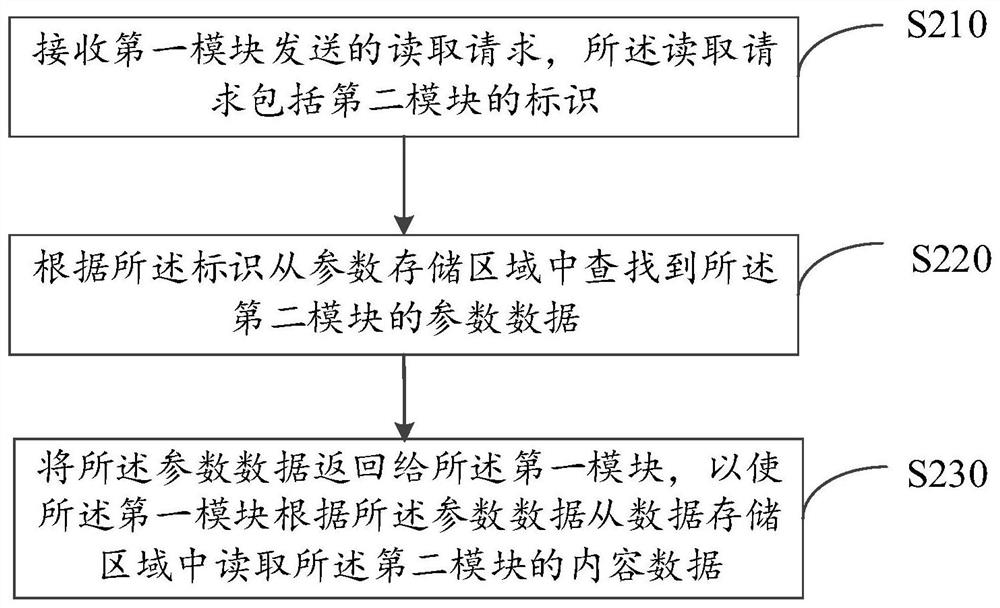
The invention provides an inter-module data transmission method, a control module and a function module. The method comprises the following steps: receiving a reading request sent by a first module, wherein the reading request comprises an identifier of a second module; searching parameter data of the second module from a parameter storage area according to the identifier; and returning the parameter data to the first module, so that the first module reads the content data of the second module from the data storage area according to the parameter data, the coupling relationship between the functional modules is broken, the upper module and the lower module are not directly connected, and the functional modules are connected with the control module. Therefore, system design requirements which cannot be realized by a pipeline technology can be met, independent debugging of each functional module is facilitated, control of an external interface on a bottom layer is facilitated, and modification times and modification contents are reduced as much as possible when codes are modified or newly added.

Description

technical field [0001] The present disclosure relates to the fields of computer technology and communication technology, and in particular to a data transmission method between modules, a control module and a function module. Background technique [0002] In the current software or hardware development process, pipeline technology is usually used. Pipeline technology is a method of data flow between modules. This method can increase the system frequency, reduce the transmission delay between registers, and ensure that the system runs at a higher clock frequency. [0003] However, this approach is only applicable when the data flow is unidirectional and the output of the previous step is the input of the next step. In this case, system debugging needs to be completed step by step, and the efficiency is relatively low. Moreover, if each functional module in the system needs to be able to interact, it is difficult to implement such a design. [0004] Moreover, in the process...

Claims


Application Information

Patent Timeline
Patent Type & Authority Applications(China)
IPC IPC(8): G06F9/34G06F9/30
CPCG06F9/34G06F9/30098
Inventor 刘歆艺
Owner 杭州迪普信息技术有限公司
Why Eureka
Try Eureka