
Novel labyrinth sealing structure and pull rod sealing system

A sealing structure and sealing system technology, which is applied in the field of aero-engines, can solve problems such as cooling the front end of the sealing rod, and achieve the effects of lowering the temperature, reducing the test cost, and reducing the amount of leakage

Active Publication Date: 2021-06-08
SHENYANG AEROSPACE UNIVERSITY
View PDF7 Cites 1 Cited by
  • Summary
  • Abstract
  • Description
  • Claims
  • Application Information

AI Technical Summary

Problems solved by technology

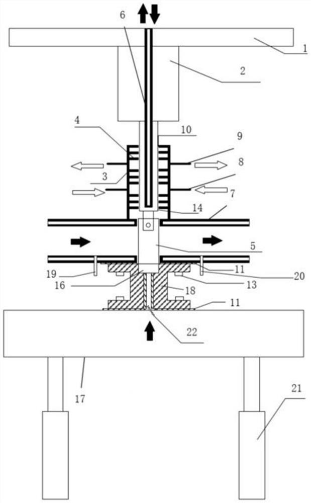
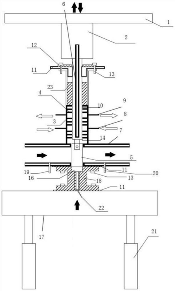
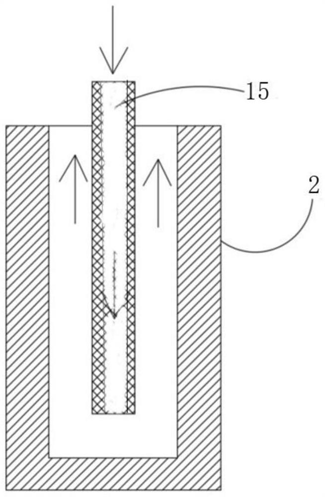
[0004] This invention provides a new type of grate tooth sealing structure and tie rod sealing system to solve the problems of sealing the experimental cabin and cooling the front end of the tie rod

Method used


Image

  • Novel labyrinth sealing structure and pull rod sealing system
  • Novel labyrinth sealing structure and pull rod sealing system
  • Novel labyrinth sealing structure and pull rod sealing system

Examples


Embodiment Construction

[0026] The technical solution of the present invention will be further described in detail below in conjunction with the accompanying drawings, but the protection scope of the present invention is not limited to the following description.

[0027] In order to make the purpose, technical solutions and advantages of the embodiments of the present invention clearer, the technical solutions in the embodiments of the present invention will be clearly and completely described below in conjunction with the accompanying drawings in the embodiments of the present invention. Obviously, the described embodiments It is some embodiments of the present invention, but not all of them. Accordingly, the following detailed description of the embodiments of the invention provided in the accompanying drawings is not intended to limit the scope of the claimed invention, but merely represents selected embodiments of the invention.

[0028] The present invention will be further described below in co...


PUM


Abstract

The invention provides a novel labyrinth sealing structure which comprises a sleeving main body and a labyrinth structure in the sleeving main body. The sleeving main body is provided with at least one air inlet hole and at least one air outlet hole which penetrate through the inside and the outside of the sleeving main body, the at least one air inlet hole is used for inputting air into the sleeving main body through an external air source, and the at least one air outlet hole is used for leading out air in the sleeving main body through an external air source. The invention further provides a pull rod sealing system using the novel labyrinth sealing structure. According to the present invention, the problems of sealing of the pull rod and cooling of the front end of the pull rod are solved.

Description

technical field [0001] The invention relates to the field of aero-engines, and more specifically relates to a novel grate tooth sealing structure and a tie rod sealing system. Background technique [0002] The thermal-mechanical coupling fatigue failure of aeroengine turbine blades is the main failure mode during aeroengine service, which seriously affects the service life of aeroengines. It is of great significance and engineering value to evaluate the design level of turbine blades and formulate the production standards of turbine blades in the industry by conducting thermal-mechanical coupling fatigue tests on turbine blades of aeroengines. [0003] In the traditional heat-mechanical coupling fatigue test methods of turbine blades, electric heating is mostly used to provide heat source, and fatigue testing machine is used to provide mechanical load. Although the currently known thermal-mechanical coupling fatigue testing machine can achieve the maximum temperature and te...

Claims


Application Information

Patent Timeline
Patent Type & Authority Applications(China)
IPC IPC(8): G01M15/02G01M15/14G01M13/00
CPCG01M15/02G01M15/14G01M13/00
Inventor 关鹏艾延廷陈英涛郜伟强田晶石炜周海仑
Owner SHENYANG AEROSPACE UNIVERSITY
Learn More