Large-mode-area microstructure optical fiber

A technology of micro-structured optical fiber and large mode field, which is applied in cladding optical fiber, multi-layer core/cladding optical fiber, etc., can solve the problems of reduced mode field area, reduced fundamental mode mode field area, and impact on use, and achieves Effects of low binding loss and low bending loss

Inactive Publication Date: 2012-06-20
JIANGSU UNIV
View PDF4 Cites 0 Cited by
  • Summary
  • Abstract
  • Description
  • Claims
  • Application Information

AI Technical Summary

Problems solved by technology

Its disadvantage is that it requires strict control of the bending direction, and the bending angle must be controlled within a very small range of a few degrees, otherwise it will lead to a rapid increase in the bending loss of the basic mode and make it unusable
Therefore, this fiber is difficult to be practical
In addition, bending will lead to a reduction in the mode field area of ​​the fundamental mode, and the smaller the bending radius, the greater the reduction in the mode field area
Therefore, although the optical fiber can allow a small bending radius, the control requirements for the bending direction and angle are very strict in actual use, which affects its actual use; in addition, the mode field area will decrease when the fiber is bent, which makes the large mode field The advantage of large mode field area of ​​optical fiber is greatly reduced

Method used


Image

  • Large-mode-area microstructure optical fiber
  • Large-mode-area microstructure optical fiber
  • Large-mode-area microstructure optical fiber

Examples


Embodiment 1

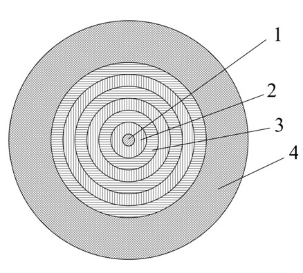
[0048] The cross-sectional structure of the optical fiber is as figure 1 shown. The matrix material is pure quartz, and the hole material is doped quartz material. Period Λ of the first type of hole 2 2 16 μm, hole diameter d 2 At 9.6 μm, the refractive index of the hole is 0.004 lower than that of the matrix material. The period Λ of the second type of hole 3 3 is 48 μm, the hole diameter d 3 At 14.4 μm, the refractive index of the hole is 0.004 lower than that of the host material. When the transmission wavelength is 1064 nm, the fundamental mode field area in the straight fiber can reach 3224 μm 2 , when the bending radius is 20 cm, the mode field area of ​​the fundamental mode is 1210.8 μm 2 . The fiber can maintain low-loss transmission at bend radii as low as 12 cm. When the fiber is straight, its fundamental mode leakage loss is less than 0.002 dB / m, and its high-order mode loss is greater than 60 dB / m. The allowable bending angle range of the optical fiber c...

Embodiment 2

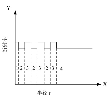
[0050] The cross-sectional structure of the optical fiber is as figure 2 shown. The matrix material is pure quartz, and the hole material is doped quartz material. The period Λ of the third type hole 4 4 is 8 μm, the hole diameter d 4 At 2.4 μm, the refractive index of the hole is 0.001 lower than that of the matrix material. Period Λ of the first type of hole 2 2 16 μm, hole diameter d 2 At 9.6 μm, the refractive index of the hole is 0.004 lower than that of the matrix material. The period Λ of the second type of hole 3 3 is 48 μm, the hole diameter d 3 At 19.2 μm, the refractive index of the hole is 0.004 lower than that of the host material. When the transmission wavelength is 1064 nm, the fundamental mode field area in straight fiber can reach 2520.7 μm 2 ; When the bending radius is 50 cm, the mode field area of ​​the fundamental mode is 2778.6 μm 2 ; When the bending radius is 30 cm, the mode field area of ​​the fundamental mode is 2204.5 μm 2 . When the fib...

Embodiment 3

[0052] The cross-sectional structure of the optical fiber is as figure 1 shown. Both the matrix material and the hole material are polymer materials. Period Λ of the first type of hole 2 2 10 μm, hole diameter d 2 At 6 μm, the refractive index of the hole is 0.006 lower than that of the matrix material. The period Λ of the second type of hole 3 3 30 μm, hole diameter d 3 At 12 μm, the refractive index of the hole is 0.006 lower than that of the matrix material. When the transmission wavelength is 633 nm, the fundamental mode field area can reach 1218.8 μm in straight fiber 2 . Its bend radius can be as low as 7.5 cm. When the fiber is straight, its fundamental mode leakage loss is less than 0.005 dB / m, and its high-order mode loss is greater than 20 dB / m. This polymer optical fiber with single-mode, large-mode field characteristics and low bending loss can be used in occasions requiring broadband and large-capacity communication in short-to-medium distance communicat...


PUM


Abstract

The invention discloses a large-mode-area microstructure optical fiber, wherein the optical fiber comprises a fiber core and a cladding layer; the cladding layer consists of a matrix material (1), first holes (2) and second holes (3); the hole centers of the first holes (2) are distributed in a 180-240 DEG sector area which takes a center of the optical fiber as a circle center; the hole centers of the second holes (2) are distributed in the other sector areas; the distance between the hole center of each of the first holes (2) and the center of the optical fiber is greater than or equal to Lambda 2; the distance between the hole centre of each of the second holes (3) and the center of the optical fiber is greater than or equal to Lambda 3; the hole period of the first holes (2) and the second holes (3) meets the following: Lambda 3 is greater than 1.5* Lambda 2; the relation of a normalized diameter meets the following: d2 / Lambda 2 is greater than d3 / Lambda 3; the interface at least has a pair of hole pitches smaller than or equal to Lambda 3; the refractive indexes of the first holes (2) and the second holes (3) are both smaller than that of the matrix material (1); the fiber core is an area encircled by the first holes (2) and the second holes (3). The optical fiber constrains the fiber core mode by using the holes in two different periods, and realizes the purposes of single-mode, large mode area, low-bending loss transmission based on the feature of light leakage when the hole with small period and large normalized diameter prevents the optical fiber from bending.

Description

technical field [0001] The invention relates to the field of optical fiber communication, in particular to a single-mode microstructure optical fiber with large mode field and low bending loss. Background technique [0002] Large mode field fibers have important applications in high-power fiber lasers, amplifiers, and intense laser transmission. It is difficult to obtain a single-mode fiber with a core diameter greater than 20 μm that works near 1064 nm using traditional fiber structures. According to the theory of optical fiber, for step-index optical fiber, to ensure that the optical fiber is single-mode transmission, the normalized frequency V of the optical fiber is required to be less than 2.405. here , a is the core radius, lambda is the wavelength of light, n c , n b are the refractive indices of the core and cladding, respectively. Therefore, for a step fiber, while increasing the core radius to increase the fiber mode field area, the refractive index diff...

Claims


Application Information

Patent Timeline
Patent Type & Authority Patents(China)
IPC IPC(8): G02B6/036
Inventor 陈明阳张永康祝远锋孙兵付晓霞
Owner JIANGSU UNIV
Why Eureka
Try Eureka