Row type continuous vacuum feeder

A vacuum feeder, continuous row type technology, applied in conveyors, conveying bulk materials, transportation and packaging, etc., can solve the problems of large vacuum source waste, unsmooth suction, waste of resources, etc., to improve conveying efficiency. , the effect of avoiding dust pollution and eliminating safety hazards

Active Publication Date: 2016-06-29
欧才权
View PDF8 Cites 0 Cited by
  • Summary
  • Abstract
  • Description
  • Claims
  • Application Information

AI Technical Summary

Problems solved by technology

[0006] There are also two defects in the electric vacuum pump as a gap-type vacuum feeder: 1) If the vacuum tube on the top of the vacuum feeder is equipped with a pneumatic three-way ball valve, there will be a large waste of vacuum source, and the vacuum source will be used to do work when the material is sucked. , and when switching to unloading, the vacuum pump is also switched by the three-way ball valve to suck the outside air without doing work, which is a waste of resources; When switching to blanking, the vacuum pump cannot suck the outside air, which will cause the vacuum degree of the vacuum pipe, vacuum tank, etc. to increase to -80 to -90KPa, which is much higher than the vacuum degree (generally -45~-60KPa) when the material is sucked. When it is switched to suction again, it will cause high vacuum to low vacuum. The material that has just been sucked in will be tightly blocked around the filter element group and the equipment cylinder, resulting in unsmooth suction. Compressed air or nitrogen is also difficult to remove clogged material
[0008] After conveying the material for a short period of time, the material cannot be sucked, because the filter element cannot complete self-cleaning during vacuum suction (use compressed air to blow off the filter hole and the surrounding material, so that the filter element is always in a smooth state), resulting in blockage. The vacuum degree in the material tube will gradually decrease, which will gradually cause the inability to absorb the material. If you want to transport it smoothly, you must frequently take out the filter element to clean it or replace it. This brings inconvenience to the user, and the drug is also exposed and Frequent contact with operators makes it impossible to use normally and meet GMP requirements

Method used


Image

  • Row type continuous vacuum feeder

Examples


Embodiment Construction

[0020] In order to make the object, technical solution and advantages of the present invention clearer, the present invention will be further described in detail below in conjunction with the accompanying drawings.

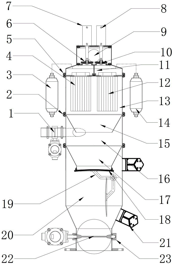
[0021] The embodiment of the present invention provides a row-type continuous vacuum feeder, such as figure 1 As shown, it includes the feeding bin 16 and the lower feeding bin 20 arranged at its lower part. One side of the feeding bin 16 is provided with a feeding port, and the feeding port is provided with a pneumatic suction butterfly valve 1. The feeding bin 16 is connected with the lower feeding port. A discharge hopper 17 is arranged between the bins 20, and the movable bottom of the discharge hopper 17 is provided with a convex top plate valve 19 and a plate valve sealing ring 18, and a discharge port is provided at the bottom of the discharge bin 20, and a pneumatic discharge butterfly valve 22 is provided on the discharge port. , a butterfly valve sealing...


PUM


Abstract

The embodiment of the present invention discloses a row-type continuous vacuum feeding machine, which includes a feeding bin and a lower bin arranged at the lower part thereof, a feeding port is provided on one side of the feeding bin, and a pneumatic feeding port is provided on the feeding port. Suction butterfly valve, there is a discharge hopper between the feeding bin and the lower bin, the movable bottom of the bin is provided with a convex top plate valve, the bottom of the lower bin is provided with a discharge port, and the discharge port is provided with a pneumatic discharge butterfly valve. There is also a filter bin on the upper part of the silo. There are two left and right bins in the filter bin; The right air duct is composed of air blowing bag, quick exhaust valve, right chamber filter element, right air door and right cylinder. The purpose of the present invention is to provide a continuous feeding, high conveying efficiency, no waste of vacuum source, allowing suction and discharge The row-type continuous vacuum feeder maintains a constant speed and smooth flow.

Description

technical field [0001] The invention relates to the field of vacuum feeders, in particular to a row-type continuous vacuum feeder. Background technique [0002] Vacuum feeding machine is also called powder conveying system (abbreviated as PTS), and it is currently in the general promotion stage at home and abroad. The equipment reduces dust pollution and saves labor. However, the vacuum feeders currently used at home and abroad are all gap-type, and there are problems such as unsmooth feeding, reverse spraying at the suction port, short conveying distance, and low efficiency. The powder transportation of high distance or large output often adopts positive pressure transportation, using high-pressure fan or compressed air to carry out positive pressure blowing to the long pipeline below which is equipped with related fans to uniformly feed materials to realize dilute phase transportation, and the end of the transportation needs to be equipped with a cyclone Separators, shut...

Claims


Application Information

Patent Timeline
Patent Type & Authority Patents(China)
IPC IPC(8): B65G53/24B65G53/58
Inventor 欧才权
Owner 欧才权
Why Eureka
Try Eureka