
Spring adjusting type sealing device for annular cooler trolley

A spring adjustment and sealing device technology, applied in the field of metallurgy, can solve problems affecting the cooling quality of sintered hot ore and waste heat recovery, large air leakage, and affecting the sealing performance of sealing devices

Active Publication Date: 2021-06-08
SHANDONG IRON & STEEL CO LTD
View PDF4 Cites 0 Cited by
  • Summary
  • Abstract
  • Description
  • Claims
  • Application Information

AI Technical Summary

Problems solved by technology

[0004] In order to solve the problem that during the use of today’s trolley sealing device, the rollers of the trolley and the inner and outer guide rails will wear and tear, resulting in uneven indentations, which will affect the sealing performance of the sealing device, resulting in large air leakage and seriously affecting the safety of sintered hot ore. To solve the problems of cooling quality and waste heat recovery, the present invention provides a spring-adjustable annular cooler trolley sealing device

Method used


Image

  • Spring adjusting type sealing device for annular cooler trolley
  • Spring adjusting type sealing device for annular cooler trolley
  • Spring adjusting type sealing device for annular cooler trolley

Examples


Embodiment Construction

[0021] In order to make the purpose, features and advantages of the present invention more obvious and understandable, the technical solutions in the present invention will be clearly and completely described below in conjunction with the accompanying drawings in this specific embodiment. Obviously, the implementation described below Examples are only some embodiments of the present invention, but not all embodiments. Based on the embodiments in this patent, all other embodiments obtained by persons of ordinary skill in the art without creative efforts fall within the protection scope of this patent.

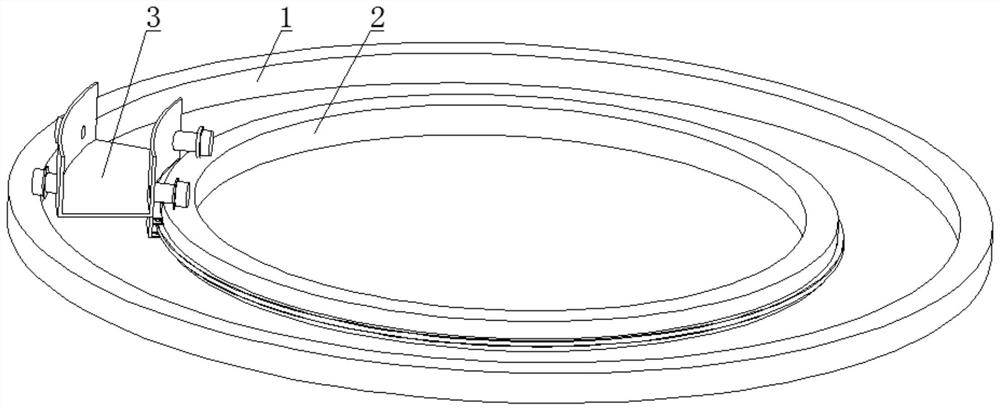
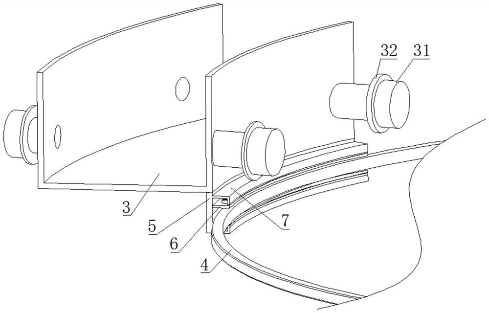
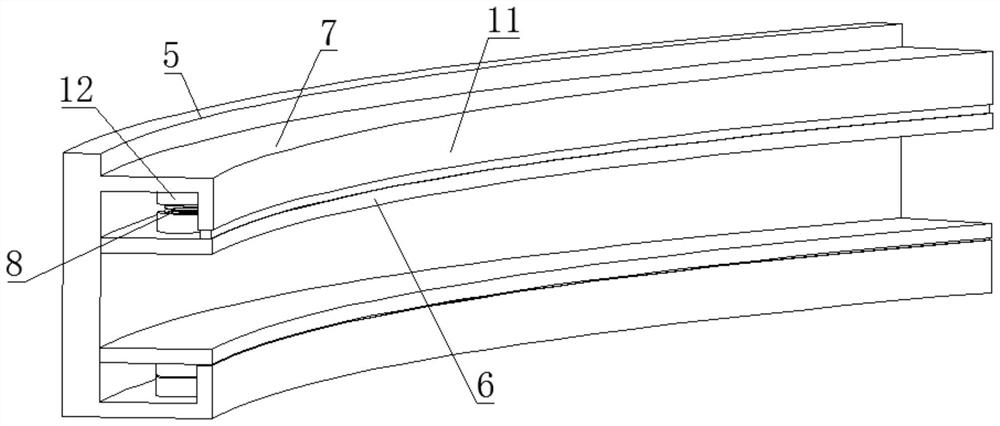
[0022] As shown in the accompanying drawings, a spring-adjustable annular cooler trolley sealing device includes an annular concentric outer guide rail 1, an inner guide rail 2, and an annular cooling trolley 3, and the outer guide rail 1 and the inner guide rail 2 are arranged horizontally; The annular cooling trolley 3 is installed between the outer guide rail 1 and the inner ...


PUM


Abstract

The invention discloses a spring adjusting type sealing device for an annular cooler trolley, and belongs to the technical field of metallurgy. The spring adjusting type sealing device for the annular cooler trolley comprises an external guide rail, an internal guide rail and the annular cooling trolley, wherein the annular cooling trolley is erected between the external guide rail and the internal guide rail, and sealing assemblies are arranged between the annular cooling trolley and the external guide rail and between the annular cooling trolley and the internal guide rail separately; each sealing assembly comprises a vertical sealing plate and a sealing ring which are fixedly connected with the annular cooling trolley; an upper sealing bottom plate and a lower sealing bottom plate are arranged at one side, far away from the annular cooling trolley, of each vertical sealing plate; sealing adjusting plates are connected to the opposite inner sides of each sealing bottom plate through return springs separately; each sealing ring is slidably arranged between the two corresponding sealing adjusting plates; and each sealing ring is connected with the internal guide rail and the external guide rail separately. The annular cooling trolley is jointly supported and guided through the external guide rail and the internal guide rail, the sealing bottom plates and the sealing adjusting plates are supported through the return springs, and the sealing adjusting plates and the sealing rings are in a tightly attached state all the time, so that a good sealing effect is ensured; and the spring adjusting type sealing device for the annular cooler trolley is high in practicability, and capable of ensuring the cooling quality for sintered hot ore, and the recovery effect for waste heat.

Description

technical field [0001] The invention belongs to the technical field of metallurgy, in particular to a spring-adjustable sealing device for a trolley of an annular cooler. Background technique [0002] The annular cooler is the abbreviation of the annular cooler. Its function is to cool the sintered hot ore unloaded from the sintering machine in time to prevent over-burning, and to recover and reuse the heat of the sintered hot ore, which can effectively avoid heat waste. The principle of the ring cooler is that the bottom of the ring cooler blows cooling air upwards, and the cooling air is heated by the sintered hot ore on the ring cooling trolley to become hot air, and is drawn out through the channel on the upper side of the ring cooler for heat recovery and reuse, thereby sintering the hot ore It can cool down in time to prevent overheating. [0003] In order to reduce the airflow at the bottom of the trolley from escaping from the surroundings and reduce the air leakage...

Claims


Application Information

Patent Timeline
IPC IPC(8): F27D15/02F27D17/00F27D99/00
CPCF27D15/02F27D17/004F27D99/0076Y02P10/25
Inventor 张戈曾晖牛福成陈书峰亓福川栾吉益陈万福董洪壮王念欣袁宇皓李雪涛王智超付廷强
Owner SHANDONG IRON & STEEL CO LTD
Learn More