
Drying structure and tentering setting machine

A technology of stenter setting machine and drying sheet, which is applied in the direction of drying machine, drying, progressive drying machine, etc., which can solve the problems of large horizontal area occupied, poor stenter effect, and inability to introduce sizing machine, etc.

Pending Publication Date: 2021-06-08
山东泰达仁信机械装备有限公司
View PDF0 Cites 0 Cited by
  • Summary
  • Abstract
  • Description
  • Claims
  • Application Information

AI Technical Summary

Problems solved by technology

Since the process involves two parts, stenter and sizing, the biggest problem of the machines on the market is the floor space. Due to the large size of the model and the many structures of equipment, often a stenter setting machine needs to occupy half of the factory building, so many small Textile mills cannot introduce more advanced and highly automated setting machines, and can only use relatively primitive equipment or equipment with poor tentering effects
The same industry has been committed to automatic corrections in the improvement of equipment, but ignored the problem of land occupation
Therefore, the existing stenter setting machine has the problem of occupying a large horizontal area

Method used

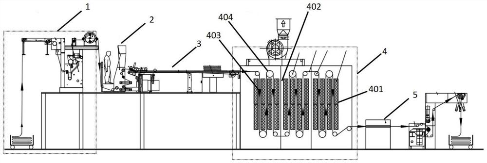
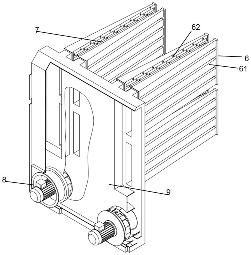
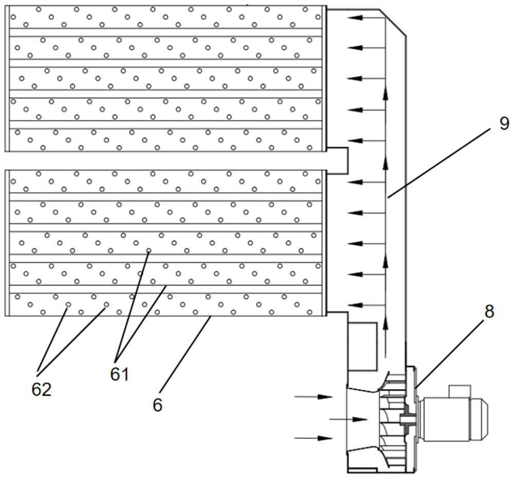

Image

  • Drying structure and tentering setting machine
  • Drying structure and tentering setting machine
  • Drying structure and tentering setting machine

Examples


Embodiment 1

[0038] Such as figure 2 , image 3 As shown, the embodiment of the present application provides a drying structure, including:

[0039] At least two drying sheets 6 arranged at intervals along the first direction, each of which extends along the second direction;

[0040] Two adjacent drying sheets form a drying channel 7, and the drying channel is used for passing the conveying bar 3 for conveying the object to be dried.

[0041] The application provides a drying structure, which forms a drying channel through the drying sheets arranged at intervals, and dries the objects to be dried through the drying channel through the conveying strip (the drying sheets on both sides of the drying channel can be dried drying), so that the space can be effectively used and the drying effect can be improved.

[0042] As a possible implementation, the drying sheets 6 arranged at intervals along the first direction can form a plurality of drying passages, wherein there are at least two dry...

Embodiment 2

[0057] Such as Figure 3-Figure 6 As shown, the embodiment of the present application provides a tenter setting machine, including the drying structure shown in the first embodiment.

[0058] As a possible implementation, it also includes: a conveying device, the conveying device includes a driving module, and a conveying strip 3 for conveying the objects to be dried, and the conveying strip passes through each of the drying channels 7 in sequence ;

[0059] The driving module is in transmission connection with the conveying bar 3, and is used to drive the conveying bar to move in the drying passage, so that the conveying bar drives the to-be-dried objects to pass through each of the drying channels in sequence. aisle.

[0060] Wherein, the conveying bar 3 can be a conveying belt, a conveying chain, and other methods capable of realizing the functions of the present application.

[0061] A possible implementation of the embodiment of the present application, the drive modul...


PUM


Abstract

The invention discloses a drying structure and a tentering setting machine. The drying structure comprises at least two drying sheets arranged at intervals along a first direction, and each drying sheet extends along a second direction; a drying channel is formed by every two adjacent drying sheets, and the drying channels are used for allowing conveying strips for conveying to-be-dried objects to pass through. The drying channel is formed through the drying sheets arranged at intervals, and the to-be-dried objects are dried through the conveying strips and the drying channel, so that a space can be effectively utilized, and the drying efficiency is improved; furthermore, when the first direction is a horizontal direction, and the second direction is perpendicular to the first direction or forms a certain included angle with the first direction, a horizontal space occupied by the drying structure can be effectively reduced.

Description

technical field [0001] The application relates to the technical field of stenter setting machines, in particular to a drying structure and a stenter setting machine. Background technique [0002] Stenter setting machine is a common textile equipment in the market at present, and it is mainly used in the tentering and setting of cloth. Since the process involves two parts, stenter and sizing, the biggest problem of the machines on the market is the floor space. Due to the large size of the model and the many structures of equipment, often a stenter setting machine needs to occupy half of the factory building, so many small Textile mills cannot introduce more advanced and highly automated setting machines, but can only use relatively primitive equipment or equipment that does not have a very good stenter effect. The same industry has been committed to automatic corrections in the improvement of equipment, but ignored the problem of land occupation. Therefore, the existing st...

Claims


Application Information

Patent Timeline
IPC IPC(8): F26B13/14F26B21/00F26B25/00
CPCF26B13/14F26B21/004F26B25/003
Inventor 李家全
Owner 山东泰达仁信机械装备有限公司
Learn More