
Ultra-low water level dynamic compaction system and method

A water level, ultra-low technology, applied in soil protection, construction, infrastructure engineering, etc., can solve the problems of large settlement, low building strength, rapid rise, etc., and achieve the effect of small settlement and high building strength after construction

Active Publication Date: 2021-06-08
JIANGSU XINTAI GEOTECHNICAL TECH CO LTD
View PDF7 Cites 0 Cited by
  • Summary
  • Abstract
  • Description
  • Claims
  • Application Information

AI Technical Summary

Problems solved by technology

When the rammer falls from a high altitude, it will have a greater impact on the soil, and the soil will quickly generate high excess pore water pressure, and the water level will also rise rapidly, which will hinder the next ramming. If the soil is not dense, it will cause Large post-construction settlement and low building strength
[0003] In the prior art, the downcomer is wrapped with a layer of filter cloth, the side wall of the downcomer is perforated, the top of the downcomer is connected to the gas-liquid separation tank and the vacuum host, and the water penetrates the filter cloth into the downcomer and is pumped away. Due to the opening of the side wall of the downcomer, the internal vacuum negative pressure is transmitted from top to bottom and decreases gradually, the seepage water at the bottom of the downcomer cannot be pumped out, and the water level cannot be lowered

Method used


Image

  • Ultra-low water level dynamic compaction system and method
  • Ultra-low water level dynamic compaction system and method
  • Ultra-low water level dynamic compaction system and method

Examples


Embodiment 1

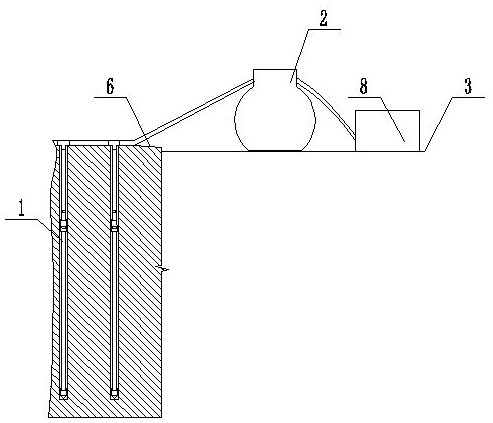
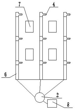
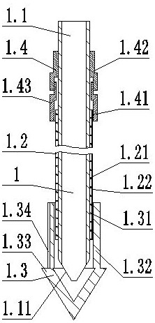
[0033] Embodiment 1: as figure 1 , 2 , 3, 4, 5, and 6, a kind of ultra-low water level dynamic compaction system includes an ultra-low water level dewatering booster pipe 1, a gas-liquid separation tank 2, a vacuum host 8, and several Holes 4, several rows of holes 4, ultra-low water level dewatering booster pipe 1 is inserted in the hole 4, the top of ultra-low water level dewatering booster tube 1 is connected to gas-liquid separation tank 2 through pipeline 6, gas-liquid separation tank 2 It is connected with the vacuum main engine 8, and several dynamic compactors 7 are arranged on the ground 3, and the dynamic compactors 7 are located between two adjacent rows of holes 4; the ultra-low water level dewatering booster pipe 1 includes a core tube 1.1, and the outer wall of the core tube 1.1 A filter tube 1.2 is provided, and the filter tube 1.2 includes a skeleton 1.21 and a filter mesh cloth 1.22 covered outside the skeleton 1.21, the skeleton 1.21 is a steel wire spiral s...

Embodiment 2

[0034] Embodiment 2: as Figure 7 As shown, a kind of ultra-low water level dynamic compaction method, inserts some ultra-low water level dewatering booster pipes 1 in the hole 4 of reinforced soil; Liquid separation tank 2, open the gas-liquid separation tank 2 and the vacuum host 8 after the connection, the water inside the reinforced land will be sucked into the gas-liquid separation tank 2, and a shaft 5 will be opened on the ground of the reinforced soil body, and the gas-liquid separation tank 2 will be placed in In the shaft 5; when the groundwater liquid level of the reinforced land falls to the water level requirement, the reinforced soil body is rammed with a dynamic tamping machine 7, several rows of ultra-low water level dewatering booster pipes 1 are inserted and arranged in parallel, and the pipeline 6 is horizontal The pipe network is arranged, the ultra-low water level dewatering booster pipe 1 is connected to the horizontal pipe network by a tee, the gas-liqui...

Embodiment 3

[0035] Embodiment 3: as Figure 8 As shown, with reference to Example 2, the gas-liquid separation tank 2 and the vacuum host 8 can be replaced by a tumbler-type water collecting device 9 for vacuum preloading with the patent number CN104294812B.


PUM


Abstract

The invention discloses an ultra-low water level dynamic compaction system. The ultra-low water level dynamic compaction system comprises ultra-low water level dewatering pressurization pipes, a gas-liquid separation tank and a vacuum main machine, wherein a plurality of formed holes are formed in the ground of a reinforced soil body, the ultra-low water level dewatering pressurization pipes are inserted into the formed holes, the tops of the ultra-low water level dewatering pressurization pipes are connected to the gas-liquid separation tank through pipelines, the gas-liquid separation tank communicates with the vacuum main machine, a plurality of dynamic compaction machines are further arranged on the ground, and the invention further discloses an ultra-low water level dynamic compaction method. According to the ultra-low water level dynamic compaction system and method, vacuum negative pressure can be conducted to the bottom of the ultra-low water level dewatering pressurizing pipes through the ultra-low water level dewatering pressurizing pipes, water enters the ultra-low water level dewatering pressurizing pipes through the bottom, ultra-low water level dewatering is achieved, then ultra-low water level dynamic compaction can be achieved through dynamic compaction of the dynamic compaction machines, settlement after construction is small, and the building strength is high.

Description

technical field [0001] The invention relates to the field of soft soil foundation treatment, in particular to an ultra-low water level dynamic compaction system and method. Background technique [0002] In the field of soft soil foundation treatment technology, dynamic compaction technology has been widely used in foundation reinforcement projects such as highways, railways, airports, and port reclamation. During the construction process, the rammer is hoisted high, and then the rammer is released to rapidly increase the bearing capacity and compression modulus of the foundation. When the rammer falls from a high altitude, it will have a greater impact on the soil, and the soil will quickly generate high excess pore water pressure, and the water level will also rise rapidly, which will hinder the next ramming. If the soil is not dense, it will cause The post-construction settlement is large and the building strength is low. [0003] In the prior art, the downcomer is wrapp...

Claims


Application Information

Patent Timeline
IPC IPC(8): E02D3/10
CPCE02D3/10E02D3/103E02D2250/0053
Inventor 钱明郑明明王敏超王小东金亚伟王军金亚军蒋君南金亚明
Owner JIANGSU XINTAI GEOTECHNICAL TECH CO LTD
Learn More