
Cut-off device of steel pipe processing machine

A technology of cutting device and processing machine, applied in the direction of pipe shearing device, accessory device of shearing machine, shearing device, etc., can solve the problems of uneven cutting of steel pipe, dangerous staff, poor clamping effect, etc., to improve work efficiency , improve the truncation effect, improve the effect of uniformity

Pending Publication Date: 2021-06-08
湖南鑫士特钢管有限公司
View PDF0 Cites 0 Cited by
  • Summary
  • Abstract
  • Description
  • Claims
  • Application Information

AI Technical Summary

Problems solved by technology

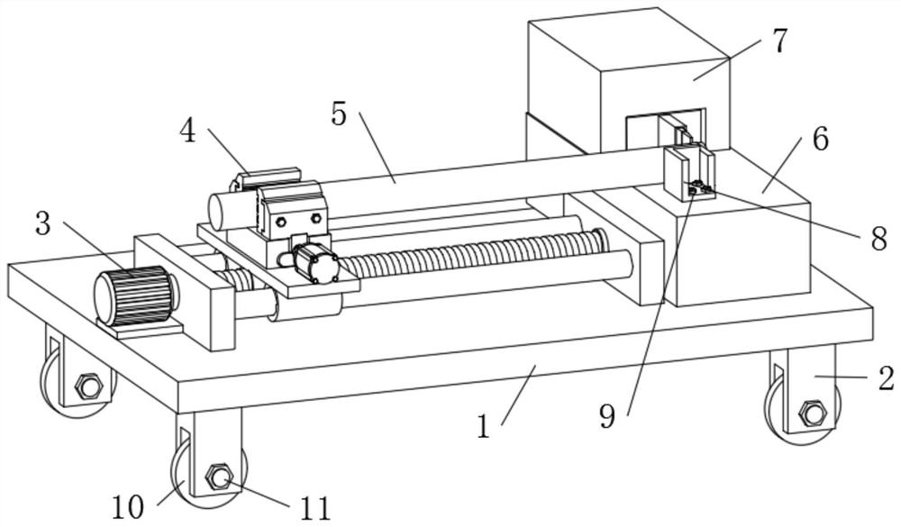
Steel pipes need to be cut from long pipes into several short pipes during production and processing. In the existing technology: 1. When the steel pipe is processed and cut off, it needs to be moved manually, because the steel pipe will shake when cut, which is easy for the staff. 2. When the steel pipe is cut off, the clamping effect is poor, so that the cutting of the steel pipe is not neat, so that the steel pipe is damaged, thereby increasing the processing cost consumption, thus causing the use of the cutting device of the steel pipe processing machine limitations, and the cut-off device of the steel pipe processing machine needs higher stability, therefore, we propose a new type of cut-off device for the steel pipe processing machine

Method used


Image

  • Cut-off device of steel pipe processing machine
  • Cut-off device of steel pipe processing machine
  • Cut-off device of steel pipe processing machine

Examples


Embodiment Construction

[0021] In order to make the technical means, creative features, goals and effects achieved by the present invention easy to understand, the present invention will be further described below in conjunction with specific embodiments.

[0022] In the description of the present invention, it should be noted that the terms "upper", "lower", "inner", "outer", "front end", "rear end", "both ends", "one end", "another end" The orientation or positional relationship indicated by etc. is based on the orientation or positional relationship shown in the drawings, and is only for the convenience of describing the present invention and simplifying the description, rather than indicating or implying that the referred device or element must have a specific orientation, use a specific Azimuth configuration and operation, therefore, should not be construed as limiting the invention. In addition, the terms "first" and "second" are used for descriptive purposes only, and should not be understood ...


PUM


Abstract

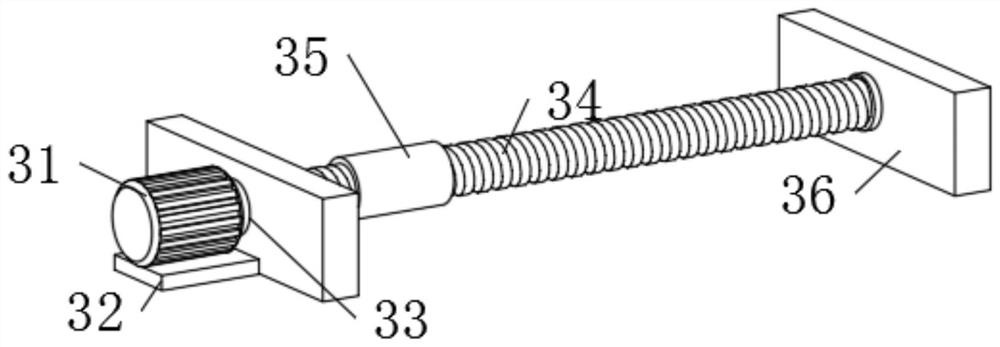
The invention discloses a cut-off device of a steel pipe processing machine. The cut-off device of the steel pipe processing machine comprises a base, supporting columns are fixedly installed on the left portion and the right portion of the lower end of the base, the four supporting columns are distributed in a bilateral symmetry mode, movable wheels are arranged at the lower ends of the four supporting columns, connecting bolts are installed at the front ends of the supporting columns in a penetrating and inserting mode, a mover is fixedly installed on the left portion of the upper end of the base, a clamping device movably sleeves the middle side of the outer surface of the mover, a stainless steel pipe is arranged at the upper end of the clamping device, a supporting seat is fixedly installed on the right portion of the upper end of the base, a limiting seat is fixedly installed on the front portion of the upper end of the supporting seat, a fixing bolt is installed at the upper end of the limiting seat in a penetrating mode, and a cut-off device is fixedly installed on the rear portion of the upper end of the supporting seat. According to the cut-off device of the steel pipe processing machine, the clamping device, the mover and the cut-off device are arranged, so that a steel pipe is convenient to move, and the steel pipe is firmer during cut-off.

Description

technical field [0001] The invention relates to the technical field of steel pipe processing equipment, in particular to a cutting device for a steel pipe processing machine. Background technique [0002] Steel pipe is a hollow long strip of round steel, which is widely used in petroleum, chemical, medical, food, light industry, mechanical instrumentation and other industrial pipelines and mechanical structural components. In addition, when the bending and torsional strength are the same, the weight is lighter, so it is also widely used in the manufacture of mechanical parts and engineering structures, and is also commonly used as furniture and kitchen utensils. Steel pipes need to be cut from long pipes into several short pipes during production and processing. In the existing technology: 1. When the steel pipe is processed and cut off, it needs to be moved manually, because the steel pipe will shake when cut, which is easy for the staff. 2. When the steel pipe is cut off,...

Claims


Application Information

Patent Timeline
Patent Type & Authority Applications(China)
IPC IPC(8): B23D21/00B23D33/02
CPCB23D21/00B23D33/02
Inventor 张亮
Owner 湖南鑫士特钢管有限公司
Learn More