Transmitting and receiving combined polarization optimization method under time-sharing complete polarization radar system
A technology of transmitting, receiving and optimizing methods, which is applied in the field of radar, and can solve the problems that it is difficult to transmit with full polarization at the same time, and can not achieve clutter and interference suppression well.
- Summary
- Abstract
- Description
- Claims
- Application Information
AI Technical Summary
Problems solved by technology
Method used
Image
Examples
Embodiment 1
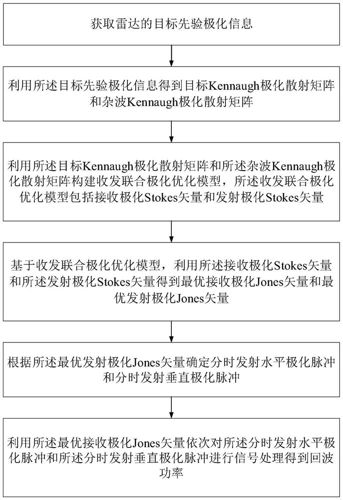
[0052] See figure 1 and figure 2 , figure 1 It is a flow chart of a joint polarization optimization method for transmission and reception under a time-sharing full-polarization radar system provided by an embodiment of the present invention, figure 2 It is a working principle diagram of the time-sharing full-polarization radar system provided by the embodiment of the present invention. An embodiment of the present invention provides a joint polarization optimization method for transmission and reception under the time-sharing full-polarization radar system, including:
[0053] Step 1. Obtain the prior polarization information of the radar target.
[0054] Specifically, the priori polarization information of the target includes: measured echo data of the first channel, measured echo data of the second channel, measured echo data of the third channel, and measured echo data of the fourth channel, wherein,
[0055] The measured echo data of the first channel is the measured e...
Embodiment 2
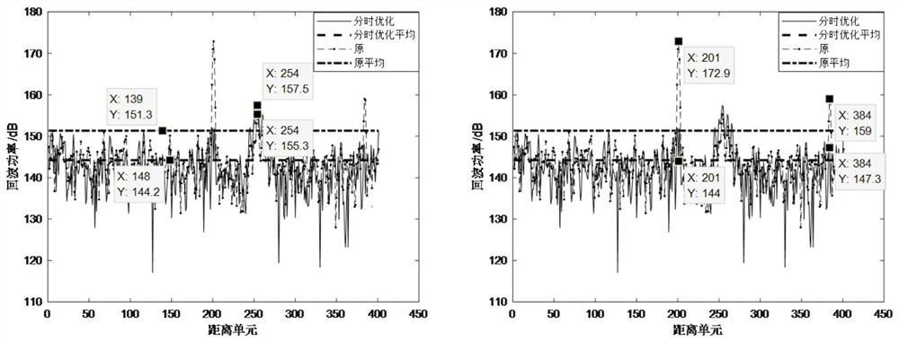
[0157] The effect of the present invention can be verified by the following simulation.
[0158] Simulation experiment parameters:
[0159] S1: Channel 0 launch, 489 meters (corner mirror), from far to near are trucks, corner mirrors and small houses, staring;
[0160] S2: Channel 1 launch, 489 meters (corner mirror), from far to near are trucks, corner mirrors and small houses, stare;
[0161] S5: channel 0 emission, 1058 meters, from far to near is transformer, angle inversion and staring;
[0162] S7: Channel 1 launch, 1058 meters, from far to near are transformers, angle inversion and staring, about 30m apart;
[0163] s1~s2: 1.2us;
[0164] s5, s7: 5us;
[0165] 1 channel is H channel emission;
[0166] 0 channel is V channel emission.
[0167] Therefore, read in S1, jc_pc_ns represents the cross-polarized pulse compression result of gaze mode, that is, VH, to_pc_ns represents the result of co-polarized pulse compression, that is, HH, and the meaning of S2 is simila...
PUM
 Abstract
Description
Claims
Application Information
 - Generate Ideas
- Intellectual Property
- Life Sciences
- Materials
- Tech Scout
- Unparalleled Data Quality
- Higher Quality Content
- 60% Fewer Hallucinations
Browse by: Latest US Patents, China's latest patents, Technical Efficacy Thesaurus, Application Domain, Technology Topic, Popular Technical Reports.
© 2025 PatSnap. All rights reserved.Legal|Privacy policy|Modern Slavery Act Transparency Statement|Sitemap|About US| Contact US: help@patsnap.com


