Coal mine tunnel support normalization auxiliary monitoring device and system based on anchor rod linkage
A technology of coal mine roadway and monitoring device, which is applied to mining devices, measuring devices, installation of bolts, etc., can solve problems such as bolt displacement, insufficient bolt installation, affecting the overall safety performance of roadway position support, etc.
- Summary
- Abstract
- Description
- Claims
- Application Information
AI Technical Summary
Problems solved by technology
Method used
Image
Examples
Embodiment 1
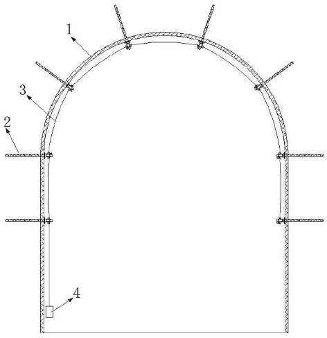
[0061] see figure 1 , there are several anchor rods 2 arranged in the roadway 1 in the figure, the exposed ends of the anchor rods 2 are tensioned and connected by the conductance stay wire 3, and the conductance stay wire 3 on the anchor rod 2 at the tail end forms a closed loop, and the conductance stay wire 3 is provided with a main processing Module 4.
[0062] The main processing module 4 is equipped with a constant voltage source module, which provides constant voltage power supply to the conductance stay wire 3 and its loop, and the main processing module 4 monitors the current information on the conductance stay wire 3 loop in real time.
[0063] The main processing module 4 is equipped with a positioning module. When the main processing module 4 detects that the anchor rod 2 on the conductance cable 3 circuit has a fixed displacement state, the positioning module is used for positioning and alarming when abnormal information occurs, which is convenient for maintenance...
Embodiment 2
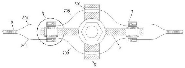
[0065] see figure 2 , the side fixing rods 6 are distributed on both sides of the main fixing base 5, the resistance mounting body 7 is arranged on the side fixing rods 6, the resistance mounting body 7 can be movably installed on the side fixing rods 6, and reinforced with nuts, The middle incoming wire 708 and the middle outgoing wire 709 move through the middle wire hole 501 of the main fixed base 5 .
[0066] The peripheral side on the resistance installation body 7 is movably connected with the stranded wire incoming wire 801 and the stranded wire outgoing wire 802 , and the stranded wire incoming wire 801 and the stranded wire outgoing wire 802 form the stranded wire body 8 .
Embodiment 3
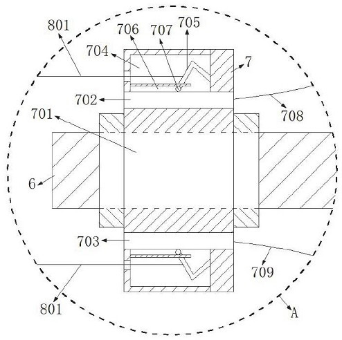
[0068] see image 3 , the resistance mounting body 7 is provided with an incoming line resistance 702 and an outgoing line resistance 703, and one side of the incoming line resistance 702 and the outgoing line resistance 703 is provided with a rheostat cavity 704, and an elastic guide piece 705 is installed in the variable resistance cavity 704, and the elastic guide piece When the 705 is subjected to the pulling force of the stranded wire incoming wire 801 or the stranded wire outgoing wire 802, it will slide on the incoming wire resistance 702 or the outgoing wire resistance 703. When sliding, the current on the electric circuit where the twisted wire body is located will change.
[0069] In addition, when the elastic guide piece 705 slides, a guide groove 706 is provided in the variable resistance cavity 704, and the guide protrusion 707 provided on the end side of the elastic guide piece 705 moves along the guide groove 706, so as to ensure that the elastic guide piece 705 ...
PUM
 Abstract
Description
Claims
Application Information
 - R&D Engineer
- R&D Manager
- IP Professional
- Industry Leading Data Capabilities
- Powerful AI technology
- Patent DNA Extraction
Browse by: Latest US Patents, China's latest patents, Technical Efficacy Thesaurus, Application Domain, Technology Topic, Popular Technical Reports.
© 2024 PatSnap. All rights reserved.Legal|Privacy policy|Modern Slavery Act Transparency Statement|Sitemap|About US| Contact US: help@patsnap.com


