
Handheld engraving tool

A tool and knife technology, applied in the field of hand-held engraving tools, can solve the problems of low safety, cumbersome operation, low work efficiency, etc., and achieve the effect of efficient transmission, efficient grinding operation, and increased work efficiency

Inactive Publication Date: 2021-06-04
杜海
View PDF0 Cites 0 Cited by
  • Summary
  • Abstract
  • Description
  • Claims
  • Application Information

AI Technical Summary

Problems solved by technology

[0003] Aiming at the above-mentioned problem, the present invention provides a hand-held engraving tool to solve the problems of cumbersome operation, low safety and low work efficiency of existing engraving tools

Method used

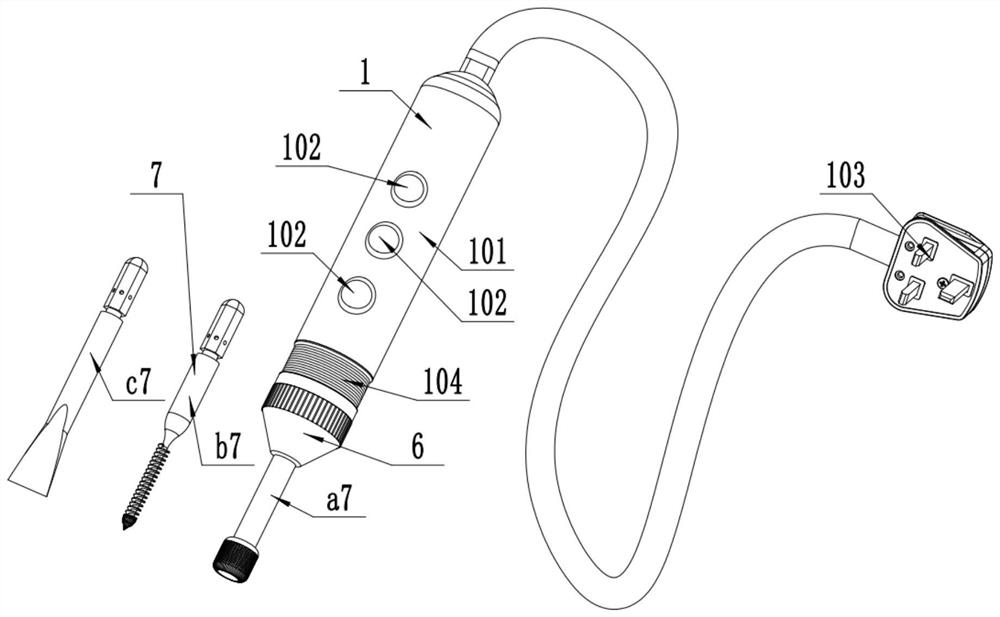
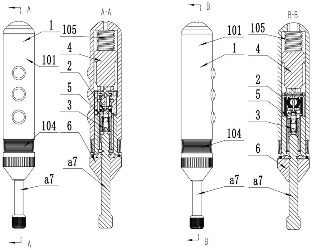
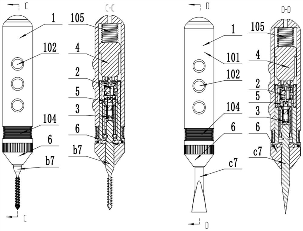

Image

  • Handheld engraving tool
  • Handheld engraving tool
  • Handheld engraving tool

Examples


Embodiment Construction

[0032]The technical solutions of the present invention will be further specifically described below through the embodiments and in conjunction with the accompanying drawings.

[0033] In the following description, many specific details are set forth in order to fully understand the present invention, but the present invention can be implemented in many other ways different from those described here, and those skilled in the art can do similar Modifications, and therefore the present invention is not limited to the specific examples disclosed below.

[0034] In the description of the present invention, it should be noted that the orientation or positional relationship indicated by the terms "up", "down", "front", "rear", "left", "right" etc. are based on the Orientation or positional relationship, or the orientation or positional relationship that the inventive product is usually placed in use, is only for the convenience of describing the present invention and simplifying the ...


PUM


Abstract

A handheld engraving tool comprises an impact part, a rotating part, a switching part and a drill bit part. The impact part enables the output force to have the back-and-forth impact force, and the impact part can be used for a flat graver. The rotating part enables the output force to be the fast rotating force, and the rotating part can be used for polishing or other tool bits. The switching part can be used for switching the force, acting on the tool bits, of a terminal to be rotating force or back-and-forth impact force or pure impact force. The handheld engraving tool is used in cooperation with the tool bits, has the self-adaptability, can automatically recognize the type of the inserted tool bits, automatically switches the type of the output force, avoids the problem that the tool bits are damaged in the using process due to the errors of manual switching, greatly improves the safety, improves the working efficiency and prolongs the service life of a machine. Various models of the drill bit parts exist, various usage scenes in the engraving operation process are met, and the drill bit part is used in cooperation with the switching part.

Description

technical field [0001] The invention relates to the field of electric tools, in particular to a hand-held engraving tool. Background technique [0002] At present, engraving machines are generally floor-standing. The overall size of the existing floor-standing engraving machines is relatively large. When processing objects to be engraved, the objects need to be fixed on the engraving machine. For the processing of engraved objects, the above-mentioned floor-standing engraving machine cannot move itself during work. The engraved object must meet the conditions of being able to be installed on the engraving machine before it can be processed, and the range of processing is limited; the structure is complex, the overall size is large, and the cost is high; it is inconvenient to move and cannot be carried. The portable engraving machine uses the mobile body itself to process the workpiece, but the working surface is limited, and it can only be processed vertically on the plane,...

Claims


Application Information

Patent Timeline
Patent Type & Authority Applications(China)
IPC IPC(8): B44B11/00
CPCB44B11/00
Inventor 杜海
Owner 杜海
Learn More