Hydraulic key puller and key pulling method using same

A hydraulic and puller technology, applied in the fields of transportation, machinery, electricity, construction, and engineering, can solve the problems of poor control of the drawing center, unreliable fixtures, low work efficiency, etc., to achieve good economic benefits and eliminate potential safety hazards , the effect of improving work efficiency

Pending Publication Date: 2021-06-04
江苏凯恩特机械设备制造有限公司
View PDF0 Cites 1 Cited by
  • Summary
  • Abstract
  • Description
  • Claims
  • Application Information

AI Technical Summary

Problems solved by technology

[0002] Some large-scale machinery, equipment, or some construction projects often encounter the need to disassemble keys, pins, rods, columns, shafts, piles and other components. Since there is no special and effective tooling, some destructive methods can only be used to do some damage. Demolition is very dangerous, labor-intensive and time-consuming, and it is difficult to achieve the desired effect and ensure safety
[0003] The magnetic pole key, an important part of the rotor of a large hydro-generator set, is a wedge plate structure. The main key and the auxiliary key are used together. Cut off, the length of the remaining exposed part is very short. During the maintenance of the unit, it is very difficult to disassemble due to the large wedging force of the key, the difficulty of clamping the head, the limited site environment, and the inability to use heavy equipment.
[0004] The method of removing the magnetic pole key during the overhaul of a large hydroelectric generator is usually to use some simple clamping tools to clamp the key head, and use the main hook of the bridge crane to forcibly pull it out. The operation is extremely inconvenient and the work efficiency is low. The pulling force is difficult to control, the pulling center is not easy to control, and the fixture is not reliable. There are many potential safety hazards. Heads will fly around uncontrollably, which can easily cause serious safety accidents, damage equipment, and endanger life

Method used


Image

  • Hydraulic key puller and key pulling method using same
  • Hydraulic key puller and key pulling method using same
  • Hydraulic key puller and key pulling method using same

Examples


Embodiment Construction

[0044] In order to make the technical means, creative features, goals and effects achieved by the present invention easy to understand, the present invention will be further described below in conjunction with specific embodiments.

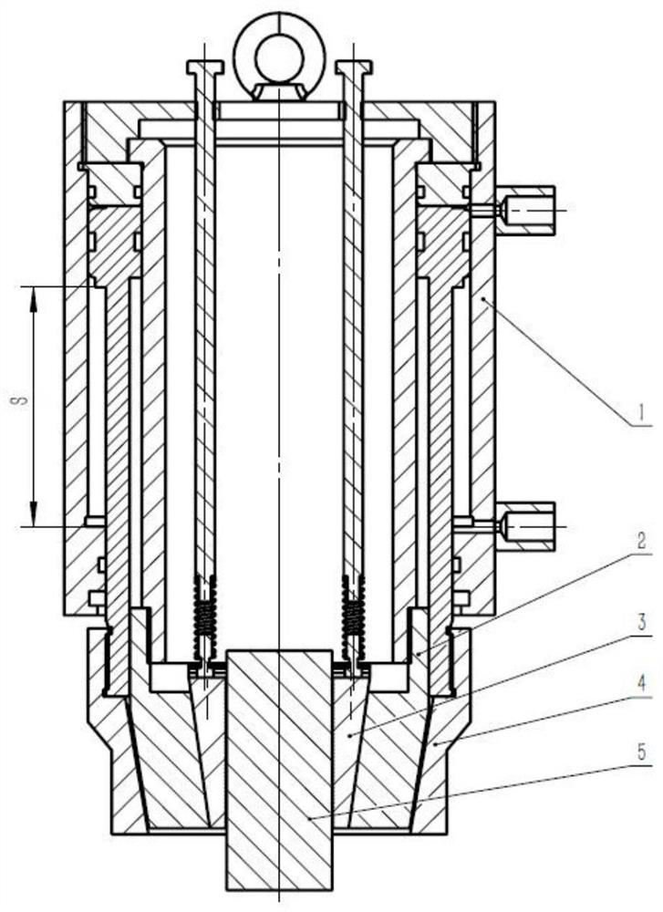
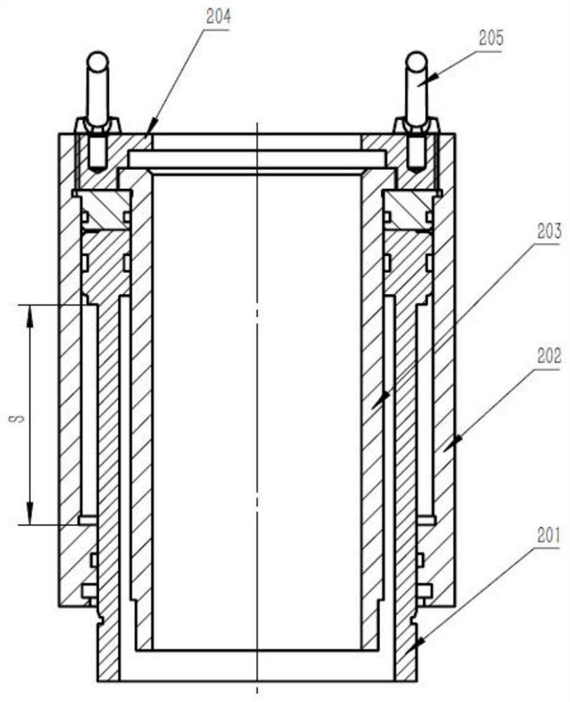
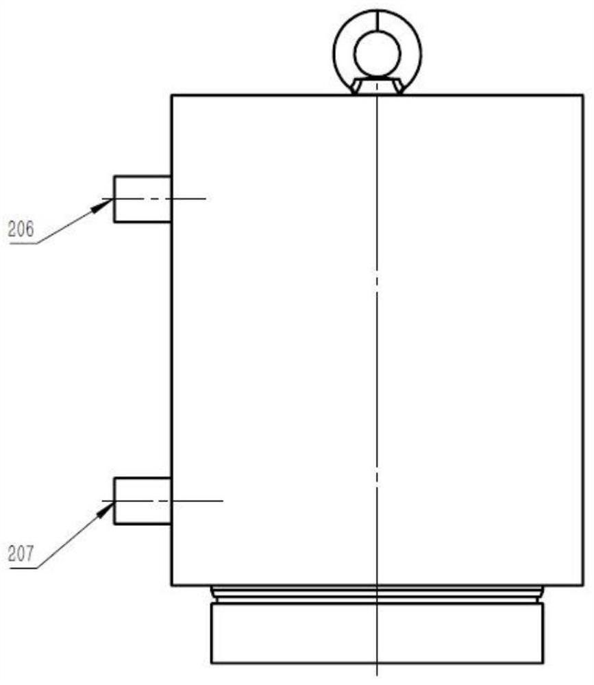
[0045] A kind of hydraulic key puller provided by the present invention, its structure is as follows figure 1 As shown, it consists of a hydraulic puller 1, a clamping block seat 2, a wedge-shaped clamping block 3 and a base 4. The hydraulic puller 1 is the core power part of the hydraulic key puller, which is a double-acting hollow hydraulic cylinder, such as figure 2 As shown, it is mainly composed of piston rod 201, outer cylinder body 202, hollow cylinder barrel 203, cylinder head 204, suspension ring 205, and some seals and guides. Such as Figure 2-Figure 6 As shown, the outer cylinder body 202 is provided with a first oil nozzle 206 and a second oil nozzle 207, and the cylinder head 204 is provided with a key outlet 208 and a threaded ho...


PUM


Abstract

The invention provides a hydraulic key puller. The hydraulic key puller is composed of a hydraulic puller, a clamping block seat, wedge-shaped clamping blocks and a base. The hydraulic puller serving as a core power part of the hydraulic key puller is a double-acting hollow hydraulic cylinder and is mainly composed of a piston rod, an outer cylinder body, a hollow cylinder barrel, a cylinder cover, a hanging ring and a number of sealing pieces and guiding pieces. A first oil nozzle and a second oil nozzle are arranged on the outer cylinder body, and a key outlet and threaded holes for fixing adjusting bolts are formed in the cylinder cover. The hydraulic key puller is compact in structure, large in pulling force, easy to operate, convenient and reliable to use and high in adaptability, and hydraulic key pullers with various dimensions, various strokes, various pulling forces and various clamping block forms can be customized according to the dimensions, shapes and other actual conditions of target keys. By the adoption of the hydraulic key puller and a key pulling method, the working efficiency can be improved, potential safety hazards can be eliminated, and good economic benefits are brought to users.

Description

technical field [0001] The invention relates to the fields of electric power, machinery, engineering, construction, transportation, etc., and in particular to magnetic keys and magnetic pole keys of generator sets in the electric power industry, and to pull out keys, pins, rods, columns, shafts, and piles in industries such as machinery, traffic, engineering, and construction. etc., more specifically relate to a hydraulic key puller and a key pull method thereof. Background technique [0002] Some large-scale machinery, equipment, or some construction projects often encounter the need to disassemble keys, pins, rods, columns, shafts, piles and other components. Since there is no special and effective tooling, some destructive methods can only be used to do some damage. Demolition is very dangerous, labor-intensive and time-consuming, and it is difficult to achieve the desired effect and ensure safety. [0003] The magnetic pole key, an important part of the rotor of a large...

Claims


Application Information

Patent Timeline
IPC IPC(8): B23P19/027B25B27/02
CPCB23P19/027B25B27/026
Inventor 李志华
Owner 江苏凯恩特机械设备制造有限公司
Why Eureka
Try Eureka