
Diode production line

A production line and diode technology, applied in the field of diodes, can solve the problems of bending and breaking of diode feet, affecting the quality of diodes, and randomly stacking diodes on one side.

Inactive Publication Date: 2021-06-04
李志猛
View PDF0 Cites 0 Cited by
  • Summary
  • Abstract
  • Description
  • Claims
  • Application Information

AI Technical Summary

Problems solved by technology

[0003] When producing diodes, it is necessary to cut and level the diode feet through equipment. During the cutting and leveling process, due to the low hardness of the diode feet, if the diode feet are directly cut, the diode feet are easy to The phenomenon of bending and breaking will affect the effect of cutting the legs of the diode, and the diodes after cutting the legs will be randomly piled up on one side, and the diode legs are easy to overlap and touch together, making the diodes cross and rub against each other, thus affecting the quality of the diodes

Method used


Image

  • Diode production line
  • Diode production line
  • Diode production line

Examples


Embodiment 1

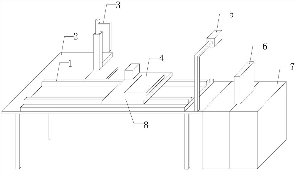
[0031] see figure 1 , the present invention provides a technical solution: a diode production line, the structure of which includes a slide rail 1, a workbench 2, a die bonder 3, a positioning device 4, a foot cutter 5, a detector 6, a main body 7, and a moving plate 8, The slide rail 1 is installed on the workbench 2, and the slide rail 1 is movably engaged with the moving plate 8. The end of the move plate 8 away from the slide rail 1 is fixedly connected with the positioning device 4. The workbench 2 and the main body 7 are connected as a whole, the main body 7 is provided with a detector 6 connected with it, and the workbench 2 is equipped with a die bonder 3 and a leg cutter 5 .

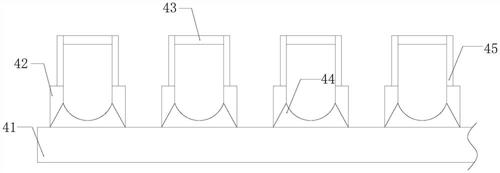
[0032] see figure 2 , the positioning device 4 includes a fixed seat 41, a cavity 42, a protective assembly 43, an adjustment clip 44, and a support rod 45, and four or more cavities 42 are installed on the fixed seat 41, four or more The cavities 42 are equally spaced and horizontally arran...

Embodiment 2

[0042] see figure 1 , the present invention provides a technical solution: a diode production line, the structure of which includes a slide rail 1, a workbench 2, a die bonder 3, a positioning device 4, a foot cutter 5, a detector 6, a main body 7, and a moving plate 8, The slide rail 1 is installed on the workbench 2, and the slide rail 1 is movably engaged with the moving plate 8. The end of the move plate 8 away from the slide rail 1 is fixedly connected with the positioning device 4. The workbench 2 and the main body 7 are connected as a whole, the main body 7 is provided with a detector 6 connected with it, and the workbench 2 is equipped with a die bonder 3 and a leg cutter 5 .

[0043] see figure 2 , the positioning device 4 includes a fixed seat 41, a cavity 42, a protective assembly 43, an adjustment clip 44, and a support rod 45, and four or more cavities 42 are installed on the fixed seat 41, four or more The cavities 42 are equally spaced and horizontally arran...


PUM


Abstract

The invention discloses a diode production line which structurally comprises a sliding rail, a workbench, a crystal bonding device, a positioning device, a pin cutting device, a detector, a body and a movable plate. When the diode production line is used, a diode is positioned through mutual cooperation of a connecting plate and a rubber pad, and a diode pin is positioned on a connecting opening, a soft rubber mat and a foam layer are matched to protect diode pins, so that the pin cutting device can quickly and stably cut the diode pins, the pin cutting effect of the diode is improved, multiple diodes are clamped and processed through multiple cavities, and the product quality of the processed diodes is improved.

Description

technical field [0001] The invention relates to the field of diodes, in particular to a diode production line. Background technique [0002] With the rapid development of society, semiconductor diodes are used more and more widely. LED lamps, also known as light-emitting diodes, are solid-state semiconductor devices that can convert electrical energy into visible light. The lamps have high luminous efficiency and low power consumption. With the advantages of less quantity and long service life, the diode cut-off is adjusted by adjusting components. When producing diodes, the areas that need to be improved are as follows: [0003] When producing diodes, it is necessary to cut and level the diode feet through equipment. During the cutting and leveling process, due to the low hardness of the diode feet, if the diode feet are directly cut, the diode feet are easy to The phenomenon of bending and fracture will affect the effect of cutting the legs of the diodes, and the diodes a...

Claims


Application Information

Patent Timeline
Patent Type & Authority Applications(China)
IPC IPC(8): B21F11/00B21C51/00B25B11/00
CPCB21C51/00B21F11/00B25B11/00
Inventor 张淑美
Owner 李志猛
Learn More