Antenna array element and ultra wide band tight coupling antenna array

An antenna array element, ultra-wideband technology, applied in the field of ultra-wideband phased array antennas, can solve problems such as radiation efficiency contradictions

Active Publication Date: 2021-06-01
SOUTHEAST UNIV +1
View PDF5 Cites 2 Cited by
  • Summary
  • Abstract
  • Description
  • Claims
  • Application Information

AI Technical Summary

Problems solved by technology

[0005] The purpose of the present invention is to provide a high radiation efficiency, ultra-wideband antenna array element and tightly coupled antenna array, to overcome the contradiction between active standing wave bandwidth and radiation efficiency of the existing ultra-wideband phased array antenna array

Method used


Image

  • Antenna array element and ultra wide band tight coupling antenna array
  • Antenna array element and ultra wide band tight coupling antenna array
  • Antenna array element and ultra wide band tight coupling antenna array

Examples


Embodiment Construction

[0024] Embodiments of the technical solutions of the present invention will be described in detail below in conjunction with the accompanying drawings. The following examples are only used to illustrate the technical solutions of the present invention more clearly, and therefore are only examples, rather than limiting the protection scope of the present invention.

[0025] It should be noted that, unless otherwise specified, the technical terms or scientific terms used in this application shall have the usual meanings understood by those skilled in the art to which the present invention belongs.

[0026] In the description of the present application, it is to be understood that the terms "horizontal", "vertical", "upper", "lower", "front", "back", "X axis", "Y axis" etc. indicate orientation Or the positional relationship is based on the orientation or positional relationship shown in the drawings, which is only for the convenience of describing the present invention and simpl...


PUM


Abstract

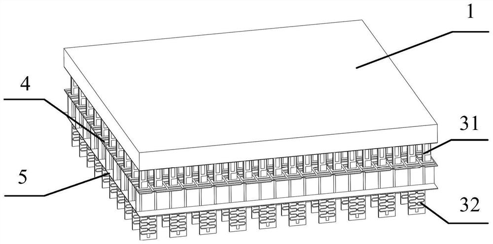
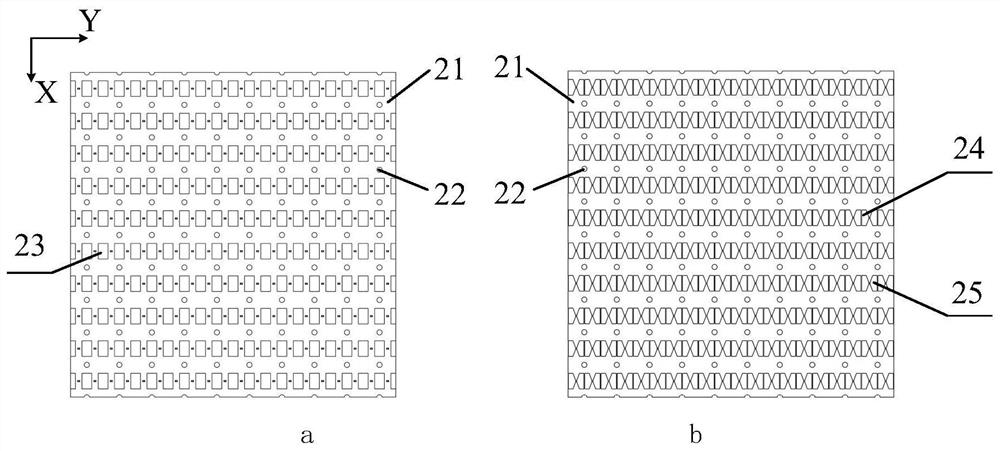
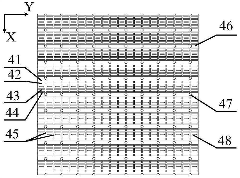
The invention discloses an antenna array element and an ultra wide band tight coupling antenna array. The antenna array element comprises a radiation unit, a feed unit and a reflection floor, and further comprises an inductive loading structure, the inductive loading structure is arranged between the radiation unit and the reflection floor, and an equivalent inductance is used for counteracting a short-circuit effect generated by the reflection floor. According to the tight coupling antenna designed by the invention, an impedance bandwidth is doubled through the inductive loading structure on the basis of not introducing loss, the antenna has relatively high radiation efficiency, the impedance bandwidth exceeds 10 octaves, the radiation efficiency is greater than 90%, and the relative bandwidth exceeds the relative bandwidth of most antenna arrays at the present stage while s relatively high radiation frequency is ensured.

Description

technical field [0001] The invention relates to the technical field of ultra-wideband phased array antennas, in particular to a tightly coupled antenna array loaded with an inductive structure. Background technique [0002] With the development of the Internet of Things and communication technology, ultra-wideband phased array antennas have received widespread attention in the field of commercial communication and detection. In the future, electronic devices not only need to perceive the surrounding environment information, but also need to adapt to changes in the surrounding environment and communicate the external environment to different terminals. This requires that the antennas of electronic devices need to work in different frequency bands to meet different functional requirements, and It has higher radiation efficiency to perceive more complete surrounding information and longer communication distance. If antennas with different operating frequencies are integrated o...

Claims


Application Information

Patent Timeline
Patent Type & Authority Applications(China)
IPC IPC(8): H01Q1/36H01Q1/50H01Q1/48H01Q21/06
CPCH01Q1/36H01Q1/50H01Q1/48H01Q21/061
Inventor 全鑫曹振新陈鹏许湘剑
Owner SOUTHEAST UNIV
Why Eureka
Try Eureka