
Temperature sensor response time testing device

A temperature sensor and testing device technology, applied in the field of sensor testing, can solve problems such as difficult enterprise application, and achieve the effects of reducing the influence of human factors, simple structure and convenient operation

Pending Publication Date: 2021-06-01
苏州福联泰克汽车电子有限公司
View PDF7 Cites 0 Cited by
  • Summary
  • Abstract
  • Description
  • Claims
  • Application Information

AI Technical Summary

Problems solved by technology

Hardly suitable for enterprise applications

Method used


Image

  • Temperature sensor response time testing device

Examples


Embodiment Construction

[0012]The present invention will be further described below with reference to the accompanying drawings.

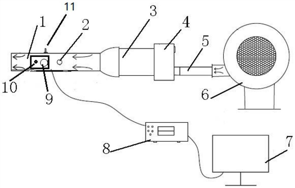
[0013]according tofigure 1The present invention is a temperature sensor response time test device including a test chamber 1, an electric heater 4, a blower 6, and a computer 7, and an exhaust port is provided on the test chamber 1, and there is an extension on the exhaust port. The tube also includes a drive device 9, the driving device 9 including a cylinder and a PLC controller, the computer 7 is disposed on the test chamber 1 side, and the computer 7 is also connected to a resistor 8, the resistor 8 pass The cable is connected to the computer 7 and the temperature sensor 10, respectively, and the computer 7 has a data acquisition processing system, and the temperature sensor 10 extends into the test chamber 1 by an extension tube, and a fixed slot is also provided on the drive device 9. The temperature sensor 10 extends into the fixed groove.

[0014]Further, the electric heater ...


PUM


Abstract

The invention provides a temperature sensor response time testing device, which comprises a testing cavity, an electric heater, an air blower and a computer, wherein the testing cavity is provided with an exhaust port, the exhaust port is connected with an extension pipe, the temperature sensor response time testing device further comprises a driving device, the driving device comprises an air cylinder and a PLC, the computer is arranged on one side of the testing cavity, one end of the computer is also connected with a resistance meter, the resistance meter is respectively connected with the computer and a temperature sensor through cables, a data acquisition and processing system is arranged in the computer, the temperature sensor extends into the testing cavity through an extension tube, the driving device is also provided with a fixed groove, and the temperature sensor extends into the fixed groove. According to the invention, the temperature sensor response time testing device is simple in structure and convenient to operate, reduces manual participation, and improves the test precision, the whole process is automatically controlled, the influence of human factors is reduced, a computer processes data quickly and accurately, a real-time curve can be generated, and the test process and result are visual.

Description

Technical field[0001]The present invention relates to the field of sensor testing techniques, and more particularly to a temperature sensor response time test device.Background technique[0002]As a super high temperature temperature sensor, its response speed is a very important indicator. The faster the response is, that is, the more sensitiveity of the sensor. Fast corresponding speeds can better control temperature, effectively reduce various losses, or even accidents due to too high temperature or less high.[0003]At present, the temperature sensor response time acquisition, most is through manual score, manually calculate, and manually calculate the cost, and inaccurate and repeatability. At the same time, there may be burnt risks when testing high temperatures. In order to ensure accuracy and reproducibility, there are also some research laboratories to measure and obtain data with high cost. It is difficult to suit the application of enterprises.Inventive content[0004]Based on ...

Claims


Application Information

Patent Timeline
Patent Type & Authority Applications(China)
IPC IPC(8): G01K15/00
CPCG01K15/007
Inventor 付联宝
Owner 苏州福联泰克汽车电子有限公司
Learn More