
A snowflake-shaped turbine blade cooling structure

A technology for turbine blades and cooling structures, applied in the direction of blade support components, machines/engines, mechanical equipment, etc., can solve the problems of uneven external air film coverage, low internal heat exchange intensity, and blade overheating, etc., to achieve the reduction of internal and external Effect of temperature difference, improvement of cooling efficiency, and improvement of uniformity

Active Publication Date: 2021-08-03
AECC SICHUAN GAS TURBINE RES INST
View PDF0 Cites 0 Cited by
  • Summary
  • Abstract
  • Description
  • Claims
  • Application Information

AI Technical Summary

Problems solved by technology

Aiming at the high thrust-to-weight ratio goal of the next-generation aeroengine, the temperature before the engine turbine will be further increased to 2300K, and the conventional impact + air film double-wall cooling structure is adopted. Compared with the tiny channel, the internal heat transfer intensity is small and the external air Uneven film coverage and other shortcomings, which will directly lead to local overheating of the blade, or even ablation

Method used


Image

  • A snowflake-shaped turbine blade cooling structure
  • A snowflake-shaped turbine blade cooling structure
  • A snowflake-shaped turbine blade cooling structure

Examples


Embodiment 1

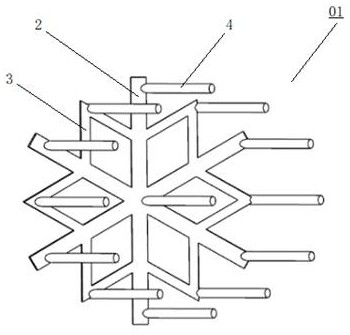
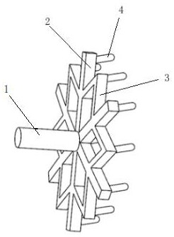
[0038] The design method of the snowflake-shaped turbine blade cooling structure of this embodiment includes the following steps:

[0039] Step 1, refer to Figure 5-Figure 6 , create a circle 1-1 with a diameter of 8mm on the XOY plane, create an inscribed equal hexagon 1-2 inside the circle 1-1, and connect lines from the center of the circle to the six corner points to form the main line 1-3, Then take the midpoints of the main line 1-3 and the midpoints of the six sides of the hexagon to connect the lines to form the branch lines 1-4; then delete the circle 1-1 and the equal hexagon 1-2 to form Image 6 shown.

[0040] Step 2: On the XOY plane, take the main line 1-3 as the center line, and offset 0.25mm to both sides to form six rectangles with a length of 4mm and a width of 0.5mm; then offset the branch lines 1-4 to both sides respectively. 0.15mm, form 12 rectangles with a length of 2mm and a width of 0.3mm, and then stretch these rectangles along the Z direction by 0.5...

Embodiment 2

[0043] The design method of the snowflake-shaped turbine blade cooling structure of this embodiment includes the following steps:

[0044] Step 1, refer to Figure 5-Figure 6 , create a circle 1-1 with a diameter of 6mm on the XOY plane, create an inscribed equal hexagon 1-2 inside the circle 1-1, and connect lines from the center of the circle to the six corner points to form the main line 1-3, Then take the midpoints of the main line 1-3 and the midpoints of the six sides of the hexagon to connect the lines to form the branch lines 1-4; then delete the circle 1-1 and the equal hexagon 1-2 to form Image 6 shown.

[0045] Step 2: On the XOY plane, take the main line 1-3 as the center line, and offset 0.25mm to both sides to form six rectangles with a length of 3mm and a width of 0.5mm; then offset the branch lines 1-4 to both sides respectively. 0.15mm, form 12 rectangles with a length of 1.5mm and a width of 0.3mm, and then stretch these rectangles along the Z direction by...


PUM


Abstract

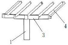
The present invention provides a cooling structure for a snowflake-shaped turbine blade, which includes a plurality of snowflake-shaped cooling units, the snowflake-shaped cooling units include cooling air supply holes, and the starting point is radially outward from the cooling air supply holes. A plurality of air supply main channels and branch channels extending radially, both sides of the middle of the main air supply channel are connected to the starting ends of the branch channels, and the ends of the branch channels are connected to the ends of the adjacent branch channels. Connected; the air film hole, the start and end of the main air supply channel, and the end of the branch channel are all connected to the air film hole. The invention can effectively increase the internal heat exchange intensity of the blade, and at the same time, the uniform air supply path can effectively reduce the temperature gradient of the blade, thereby improving the temperature bearing capacity of the blade.

Description

technical field [0001] The present disclosure relates to the technical field of gas turbine turbine blades, and in particular, to a cooling structure for a snowflake-shaped turbine blade. Background technique [0002] Turbine blade cooling technology has always been a key technology for improving gas turbine performance. The development trend of ultra-cold blade structure at home and abroad is from single-layer wall cooling to multi-layer wall cooling, from simple convection cooling to complex impact + film cooling, the cooling efficiency of the blade has also increased from 0.60 to 0.72, and the temperature bearing capacity of the blade has also increased from 1800K Boost to 2100K. For the high thrust-to-weight ratio target of the next-generation aero-engine, the temperature before the engine turbine will be further increased to 2300K. The conventional impact + air film double-wall cooling structure is adopted. The disadvantages of uneven film coverage, etc., will directl...

Claims


Application Information

Patent Timeline
Patent Type & Authority Patents(China)
IPC IPC(8): F01D5/18
CPCF01D5/186
Inventor 黄维娜郭文娄德仓苏云亮陈磊张灵俊杨双
Owner AECC SICHUAN GAS TURBINE RES INST
Learn More