Device and method for compensating dynamic contour error of machine tool

A compensation device, dynamic contour technology, applied in the direction of automatic control device, feeding device, metal processing machinery parts, etc., can solve the problem of workpiece dynamic contour error, deterioration of workpiece surface, etc.

Active Publication Date: 2022-08-05
HUAZHONG UNIV OF SCI & TECH
View PDF6 Cites 0 Cited by
  • Summary
  • Abstract
  • Description
  • Claims
  • Application Information

AI Technical Summary

Problems solved by technology

[0006] Aiming at the defects of the prior art, the object of the present invention is to provide a compensation device and method for the dynamic contour error of the machine tool, aiming at solving the relative motion caused by the tracking error between the cutting tool and the workpiece in the existing rocking vibration, resulting in Dynamic contour errors are generated on the workpiece, which in turn worsens the problem of the workpiece machined surface

Method used


Image

  • Device and method for compensating dynamic contour error of machine tool
  • Device and method for compensating dynamic contour error of machine tool
  • Device and method for compensating dynamic contour error of machine tool

Examples


Embodiment Construction

[0032] In order to make the objectives, technical solutions and advantages of the present invention clearer, the present invention will be further described in detail below with reference to the accompanying drawings and embodiments. It should be understood that the specific embodiments described herein are only used to explain the present invention, but not to limit the present invention.

[0033] The core of the present invention is as follows:

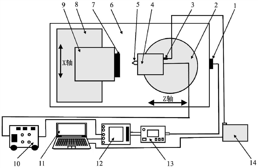
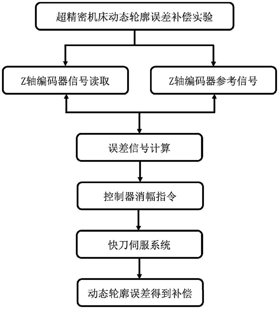
[0034] The invention provides a compensation device and method for dynamic contour error of a machine tool, thereby reducing the dynamic contour error in ultra-precision machining. First, the single-degree-of-freedom FTS (fast tool serve) system is used to extract the z-axis position error of the ultra-precision machine tool in real time, and then the extracted error signal is input to the control module of the fast tool servo system as the FTS amplitude control command , forming a closed-loop compensation system, so as to realize ...


PUM


Abstract

The invention provides a device and method for compensating dynamic contour error of a machine tool, belonging to the field of ultra-precision machining. Two square wave signals; distinguish the direction according to the phase difference of the two square wave signals, and count the number of pulses; after the count value is converted into an analog voltage, it is subtracted from the set standard voltage to obtain the inertial vibration error; The inertial vibration error is amplified as a control command; the control command is a control voltage; the control voltage is converted into mechanical energy, so that the fast tool servo system drives the tool to vibrate, thereby compensating for the inertial vibration error. The invention avoids the dynamic contour error on the workpiece and greatly improves the machining accuracy of the workpiece.

Description

technical field [0001] The invention belongs to the field of ultra-precision machining, and more particularly, relates to a compensation device and method for a dynamic contour error of a machine tool. Background technique [0002] Ultra-precision machining of surface microstructures and complex optical surfaces requires extremely precise motion control of ultra-precision machine tools. In the process of micro / nano machining, in order to meet the requirements of geometric accuracy, the influence of ultra-precision machine tools needs to be mitigated, and installation is usually required. However, a major disadvantage of passive vibration isolators is low stiffness, which is difficult to support the inertial force of each axis in motion , the worktable is supported by this isolator which is equivalent to a soft spring. When the machine tool table accelerates or decelerates in motion, the inertial force of the machine tool table excites the vibration of the machine tool struc...

Claims


Application Information

Patent Timeline
Patent Type & Authority Patents(China)
IPC IPC(8): B23Q17/20B23Q15/12
CPCB23Q17/20B23Q15/12
Inventor 张建国许剑锋李江黄凯陈肖肖峻峰
Owner HUAZHONG UNIV OF SCI & TECH
Why Eureka
Try Eureka