Method and system for automatically calibrating shunt

An automatic calibration and shunt technology, which is applied in the direction of instruments, measuring devices, and measuring electrical variables, etc., can solve the problems of low calibration accuracy and efficiency, complicated shunt calibration operation, and inability to realize digital calibration, so as to improve efficiency and digitalization Calibration levels, improved accuracy, and the effect of simplifying calibration operations

Active Publication Date: 2021-05-28
YUNNAN INST OF MEASUREMENT TEST TECH RES
View PDF15 Cites 2 Cited by
  • Summary
  • Abstract
  • Description
  • Claims
  • Application Information

AI Technical Summary

Problems solved by technology

In order to solve the existing shunt calibration operation complexity, low calibration accuracy and efficiency, and the inability to realize digital calibration problems

Method used


Image

  • Method and system for automatically calibrating shunt
  • Method and system for automatically calibrating shunt
  • Method and system for automatically calibrating shunt

Examples


Embodiment Construction

[0048]The embodiments will be described in detail hereinafter, examples of which are illustrated in the accompanying drawings. When the following description refers to the accompanying drawings, the same numerals in different drawings refer to the same or similar elements unless otherwise indicated. The implementations described in the following examples do not represent all implementations consistent with this application. These are merely examples of systems and methods consistent with aspects of the present application as recited in the claims.

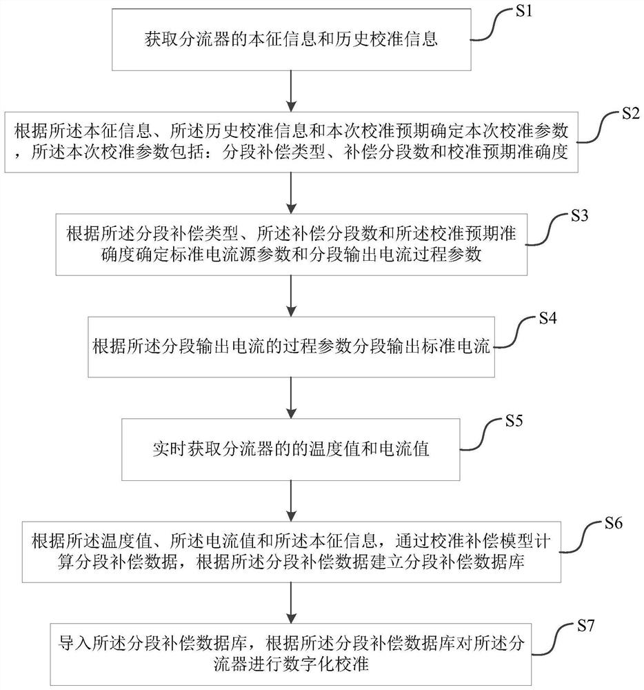
[0049] see figure 1 , figure 1 It is a flow chart of an embodiment of a method for automatic calibration of a shunt provided in this application. In one aspect, the present application provides a method for automatic calibration of a shunt, including:

[0050] S1: Obtain the intrinsic information and historical calibration information of the shunt.

[0051] In some embodiments, optionally, the intrinsic information includes: a...


PUM


Abstract

The invention provides a method and system for automatically calibrating a shunt. The method comprises the following steps: acquiring intrinsic information and historical calibration information of a shunt; determining current calibration parameters according to the intrinsic information, the historical calibration information and the current calibration expectation, the current calibration parameters comprising a segment compensation type, a compensation segment number and calibration expectation accuracy; determining a standard current source parameter and a process parameter of segmented output current according to the current calibration parameter, and outputting a standard current in a segmented manner; acquiring a temperature value and a current value of the shunt in real time; calculating segmented compensation data through the calibration compensation model, and establishing a segmented compensation database; and inputting the segmented compensation database to carry out digital calibration on the shunt. establishing different types of segmented compensation databases by classifying and testing the shunt, and importing the segmented compensation databases of the corresponding types to carry out digital calibration on the shunts. And aiming at batch shunt calibration, the calibration operation can be simplified, the calibration efficiency is improved, and the calibration accuracy and the digital level are improved.

Description

technical field [0001] The invention belongs to the technical field of electricity measurement and informationization, and in particular relates to a method and system for automatic calibration of a shunt. Background technique [0002] The shunt is a sensor device for measuring DC current, which is used for DC large current measurement. A high-power shunt is mainly composed of a low-value resistor. According to Ohm's theorem, when a DC current flows through the shunt, a voltage drop occurs across the shunt resistor. By measuring the voltage drop across the shunt resistor, the current value can be calculated. Due to the advantages of simple structure, reliable operation, stable performance, and low cost, shunts are widely used in DC current measurement in fields such as high-power chargers, high-power rectifiers, high-power inverters, and battery energy storage. [0003] However, in practical applications, shunts have problems such as low measurement accuracy, large heat gen...

Claims


Application Information

Patent Timeline
Patent Type & Authority Applications(China)
IPC IPC(8): G01R35/00
CPCG01R35/005
Inventor 王玉元张自长徐万成阮俊李亚娟
Owner YUNNAN INST OF MEASUREMENT TEST TECH RES
Why Eureka
Try Eureka