Furnace end of vaporized fuel oil combustion furnace

A technology for burning furnaces and burners, which is applied in the directions of burners, combustion methods, combustion types, etc., and can solve the problems of easy blockage, inconvenient use, and inability to adapt to conversion and use.

Pending Publication Date: 2021-05-28
邓光勇 +2
View PDF0 Cites 0 Cited by
  • Summary
  • Abstract
  • Description
  • Claims
  • Application Information

AI Technical Summary

Problems solved by technology

[0003] The currently used alcohol-based gasification burner, vaporized fuel oil burner burner burner burner burner burner burner nozzle sprays a large amount of vaporized fuel oil, while hotels, restaurants, guesthouses, school canteens, etc. use vaporized fuel burner burner burner burner burners with different fuel injection volumes. Similarly, due to the particularity of alcohol-based vaporized fuel combustion, the burner head of the same vaporized fuel burner cannot meet the requirements of switching between hotels, restaurants, hotels, and school cafeterias by adjusting the fire valve of the vaporized furnace. It is necessary to produce different fuel injection quantities or Model vaporized fuel burner burner head, resulting in high production cost and inconvenient
[0004] Secondly, the carbon deposition in the process of alcohol-based fuel gasification combustion accumulates on the furnace wall, and the components of the alcohol-based gasification combustion furnace are easily blocked, resulting in the failure of the alcohol-based gasification combustion furnace to work normally, high maintenance costs, and inconvenient use

Method used


Image

  • Furnace end of vaporized fuel oil combustion furnace
  • Furnace end of vaporized fuel oil combustion furnace
  • Furnace end of vaporized fuel oil combustion furnace

Examples


Embodiment Construction

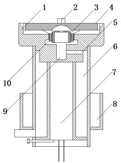
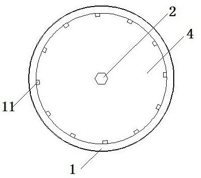
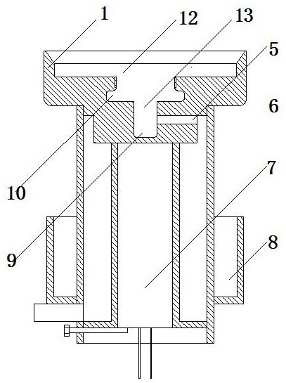
[0033] The present invention is described in detail below in conjunction with accompanying drawing and specific embodiment:

[0034] like figure 1 , figure 2 , image 3 , Figure 4 , Figure 5 , Image 6 As shown, the gasification fuel burner burner head of the present invention includes a flame injection sleeve 1 and a flame injection head. The fire spray sleeve 1 is provided with a placement chamber 12 for placing the fire spray head. The bottom of the placement chamber 12 is provided with a communication chamber 13 . The side wall of the communication chamber 13 is provided with an air inlet 5 . One end of the air inlet channel 5 communicates with the communication cavity 13 and the other end communicates with the air source. The fire head includes a splitter plate 4 , a guide cavity 15 and an adjustment cylinder 14 . The splitter plate 4 is sealed on the top of the placement cavity 12 . The splitter plate 4 is provided with jet splitter channels 11 and guide hol...


PUM


Abstract

The invention discloses a furnace end of a vaporized fuel oil combustion furnace. The furnace end comprises a fire spraying sleeve and a fire spraying head; the fire spraying sleeve is provided with a placing cavity for placing the fire spraying head; a communicating cavity is formed in the bottom of the placing cavity, and an air inlet channel is formed in the side wall of the communicating cavity; one end of the air inlet channel communicates with the communicating cavity, and the other end of the air inlet channel communicates with an air source; the fire spraying head comprises a splitter plate, a guide cavity and an adjusting cylinder; the splitter plate is sealed at the top of the placing cavity; the splitter plate is provided with an air injection sub-runner and a flow guide hole; an outlet of the gas injection sub-runner points to a combustion cavity of an alcohol-based gasification furnace, and an inlet of the gas injection sub-runner communicates with the placing cavity; the flow guide hole is formed in the bottom of the splitter plate, and two ends of the flow guide hole communicate with the guide cavity and the placing cavity respectively; the guide cavity is fixed at the bottom of the splitter plate and the top of the guide cavity is sealed; and the lower bottom of the adjusting cylinder is open, the upper bottom of the adjusting cylinder is sealed and is provided with a vent hole, the upper end of the adjusting cylinder is arranged in the guide cavity and is in threaded connection with the inner wall of the guide cavity, and the lower end of the adjusting cylinder communicates with a communication cavity.

Description

technical field [0001] The invention relates to a combustion stove, in particular to a burner head of a gasification fuel combustion furnace. Background technique [0002] Alcohol-based fuel (methanol fuel) has the advantages of low fuel consumption, much higher firepower than liquefied petroleum gas, more economical use, safety, and environmental protection. It is widely used in hotels, restaurants, guesthouses, school canteens, fast food, restaurants, etc. Alcohol-based gasification combustion furnaces have also gradually developed. [0003] The currently used alcohol-based gasification burner, vaporized fuel oil burner burner burner burner burner burner burner nozzle sprays a large amount of vaporized fuel oil, while hotels, restaurants, guesthouses, school canteens, etc. use vaporized fuel burner burner burner burner burners with different fuel injection volumes. Similarly, due to the particularity of alcohol-based vaporized fuel combustion, the burner head of the same ...

Claims


Application Information

Patent Timeline
Patent Type & Authority Applications(China)
IPC IPC(8): F23D11/22F23D11/36F23D11/44F23D11/42
CPCF23D11/22F23D11/36F23D11/448F23D11/42
Inventor 邓光勇张春龙禤赞明
Owner 邓光勇
Why Eureka
Try Eureka