Sliding type air valve

An air valve and sliding type technology, which is applied in the direction of lifting valve, valve device, valve details, etc., can solve the problems of large installation space, no position indication signal transmission, and automatic valve cannot be opened normally, so as to avoid failure and increase Effects of Sensitivity and Accuracy

Active Publication Date: 2021-05-28
ANDRITZ CHINA
View PDF7 Cites 0 Cited by
  • Summary
  • Abstract
  • Description
  • Claims
  • Application Information

AI Technical Summary

Problems solved by technology

[0003] There are mainly two types of air valves that can achieve the above functions. One is to realize this function through a floating structure. The valve body of the floating air valve needs to be connected with the volute of the water turbine or the water distribution ring pipe. Under the action of buoyancy, it moves up with the water surface to the end of the path, and at the same time closes the passage to realize water sealing; when draining water, the floating piston descends with the water surface, thereby opening the passage to realize air replenishment. The disadvantage of this structure is that it requires a large installation space and is not easy It is suitable for installation on pipelines with small diameters, and it also poses great challenges to the layout
[0004] The other is a spring automatic valve with a relatively simple structure. The above functions are realized by a single spring. Unreasonable, the water inlet hole of the water flow automatic closing action chamber is too small, it is easy to be blocked by sediment, and it has high requirements on water quality. In addition, this spring automatic valve does not have the function of transmitting the position indication signal, so it cannot be blocked when a fault occurs. discovered in time

Method used


Image

  • Sliding type air valve
  • Sliding type air valve
  • Sliding type air valve

Examples


Embodiment Construction

[0033] The sliding air valve provided by the present invention will be described in detail below with reference to the accompanying drawings.

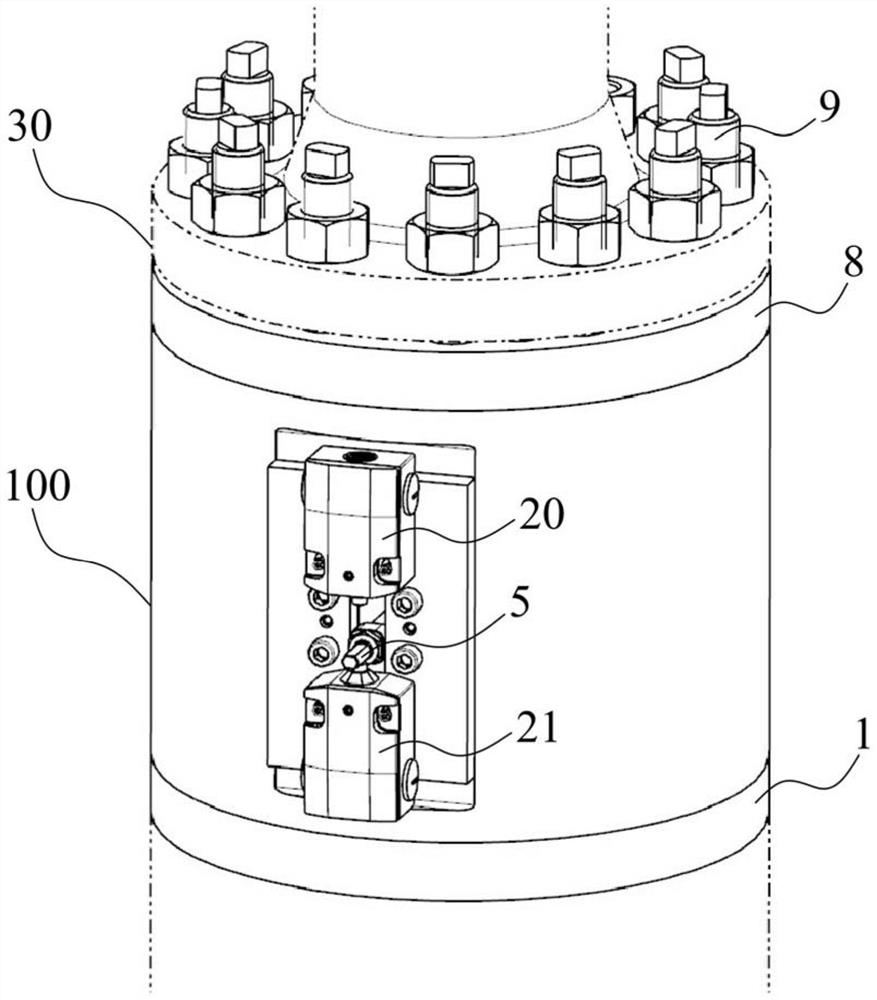
[0034] figure 1 The slide-type air valve 100 according to the invention is shown schematically in an installed state. As shown in the figure, the sliding air valve 100 provided by the present invention has a vertical structure as a whole, and is installed on the water distribution ring pipe of the impact type turbine or the volute drainage and exhaust pipeline 30 of the mixed flow turbine. During the air process, the sliding air valve 100 can be precisely closed and opened.

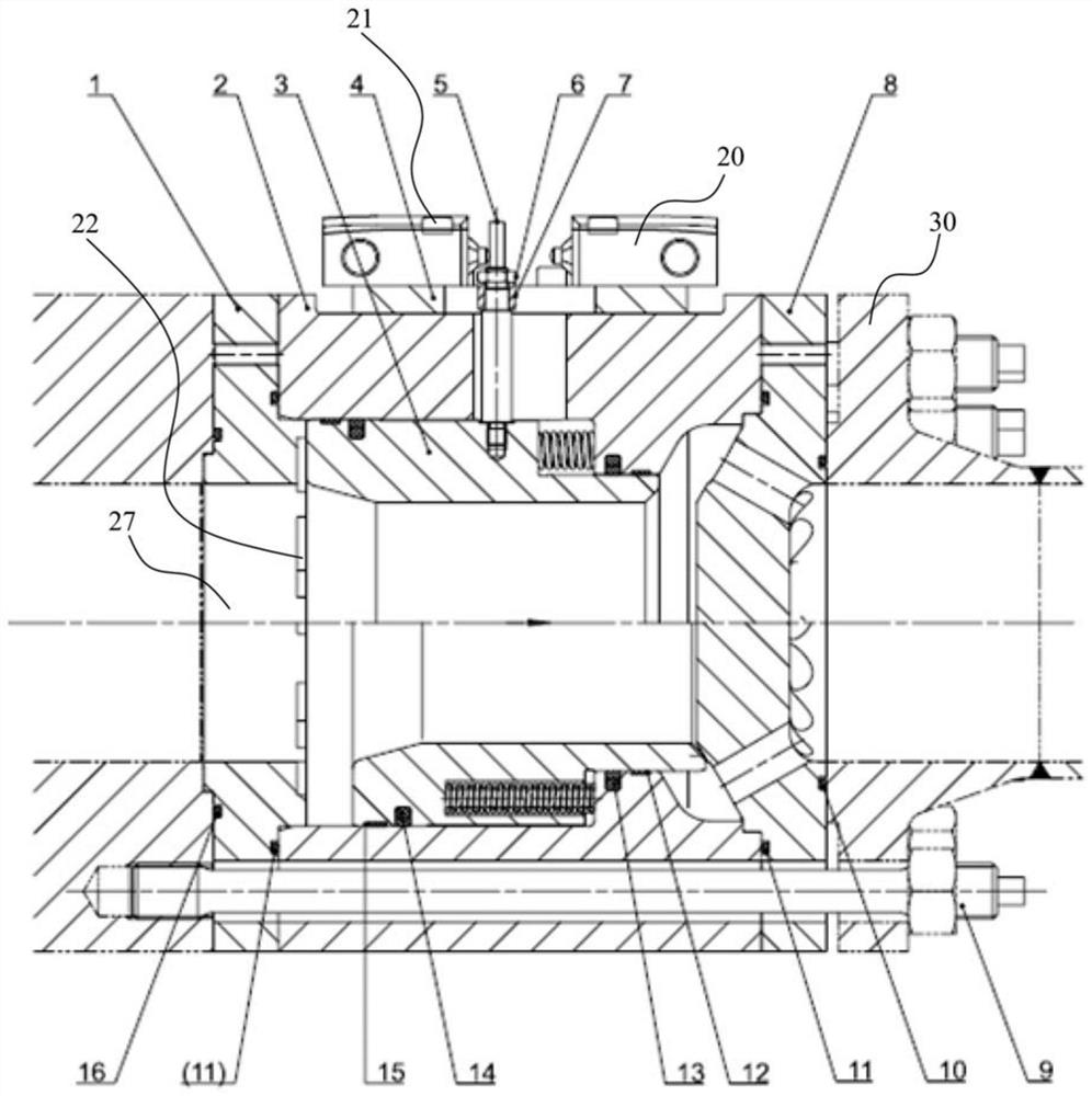
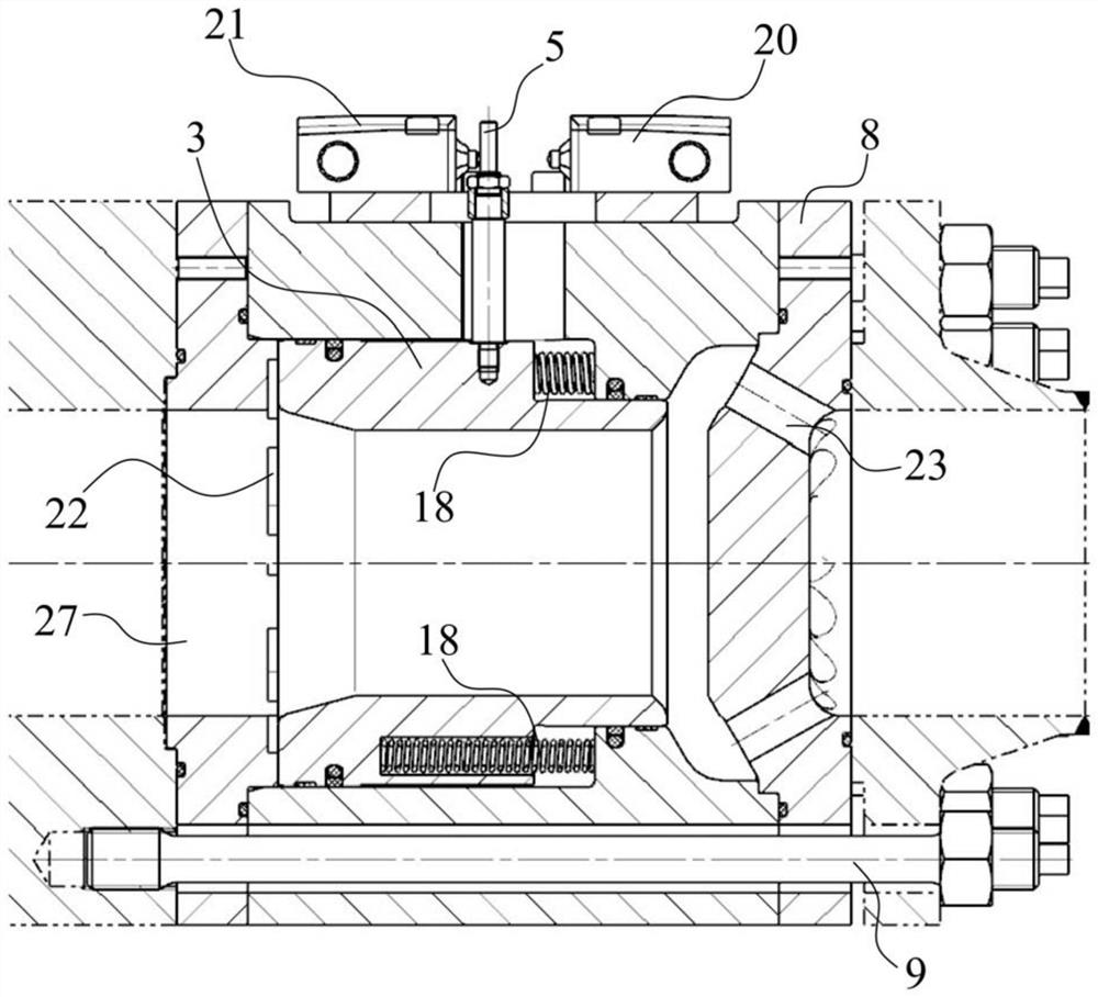
[0035] As shown in the figure, the position switch is firstly connected to the connecting plate 4 by bolts, and then installed on the valve body 2 as a whole. When pre-assembling in the factory, first install the connecting plate 4 on the valve body, then adjust the positions of the position switches 20 and 21 according to the fully open and fully closed positi...


PUM


Abstract

The present invention relates to a sliding type air valve. The sliding type air valve is vertically mounted and comprises: a valve body (2); a water inlet end cover (1), wherein the water inlet end cover is arranged at the water inlet end of the valve body; a flow guide plate (8), wherein the flow guide plate is arranged at the water outlet end, opposite to the water inlet end, of the valve body; and a piston (3). An elastic reset device is arranged between the piston and the valve body, the elastic reset device provides elastic reset force enabling the piston to move towards the water inlet end cover, and loads are preloaded to the degree that the piston abuts against the water inlet end cover in the state that no water pressure exists in the sliding type air valve so that the piston can reach the valve full-open position of the sliding type air valve. Multiple concave action grooves (22) communicating with an inner hole (27) of the water inlet end cover are formed in one side, facing the piston, of the water inlet end cover. The pressure difference generated by all the areas, corresponding to the concave action grooves, of a water inlet end face of the piston and the area of a water outlet end face of the piston under the action of fluid in a flow channel is larger than elastic reset force capable of being provided by the elastic reset device.

Description

technical field [0001] The invention relates to a sliding air valve, in particular to a sliding air valve installed vertically on a water distribution ring pipe or a drainage and exhaust pipeline of a water turbine. Background technique [0002] At present, whether it is a conventional impact turbine water distribution ring or a Francis turbine volute, the air in the flow channel needs to be emptied during the water filling process, and the air should be closed and sealed in time when the air is emptied; During the process, it is necessary to supplement the air in the flow channel, and the supplemented air plays a role in balancing the flow channel and the external atmospheric pressure. The above functions usually need to be realized through the air valve. During the process of water filling and exhausting, drainage and air replenishment, whether the air valve can be accurately closed or opened will directly affect the operation stability of the entire unit and the safety of...

Claims


Application Information

Patent Timeline
Patent Type & Authority Applications(China)
IPC IPC(8): F16K1/00F16K1/32F16K1/38F16K27/02F16K31/122F16K37/00F16K47/08F16L55/07
CPCF16K1/00F16K1/32F16K1/385F16K27/0254F16K31/1221F16K37/0083F16K47/08F16L55/07
Inventor 刘璐莎武振波李伟刘君
Owner ANDRITZ CHINA
Why Eureka
Try Eureka