A device and method for retreating grouting

A retreating, grouting technology, applied in soil protection, construction, infrastructure engineering, etc., can solve the problem that the grouting effect cannot be effectively guaranteed, the pressure of grouting cannot go up, the soil body collapses in the hole wall, etc. problem, to achieve the effect of low cost of production materials, convenient operation, and accurate adjustment.

Active Publication Date: 2022-03-15
SHANDONG UNIV OF SCI & TECH +2
View PDF10 Cites 2 Cited by
  • Summary
  • Abstract
  • Description
  • Claims
  • Application Information

AI Technical Summary

Problems solved by technology

[0004] However, the inventor found that the disadvantages of this retreating grouting device are: if the plugging pressure is high, the plugging will squeeze the surrounding soil, causing the soil on the hole wall to collapse, and the grouting pipe is buried in the hole ; If the plugging pressure is reduced to make the plugging pressure small, the grouting pressure cannot be increased, and the grouting effect cannot be effectively guaranteed

Method used


Image

  • A device and method for retreating grouting
  • A device and method for retreating grouting
  • A device and method for retreating grouting

Examples


Embodiment 1

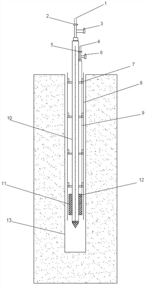
[0046] In a typical embodiment of the present invention, refer to figure 1 and figure 2 As shown, a device for retreating grouting, including:

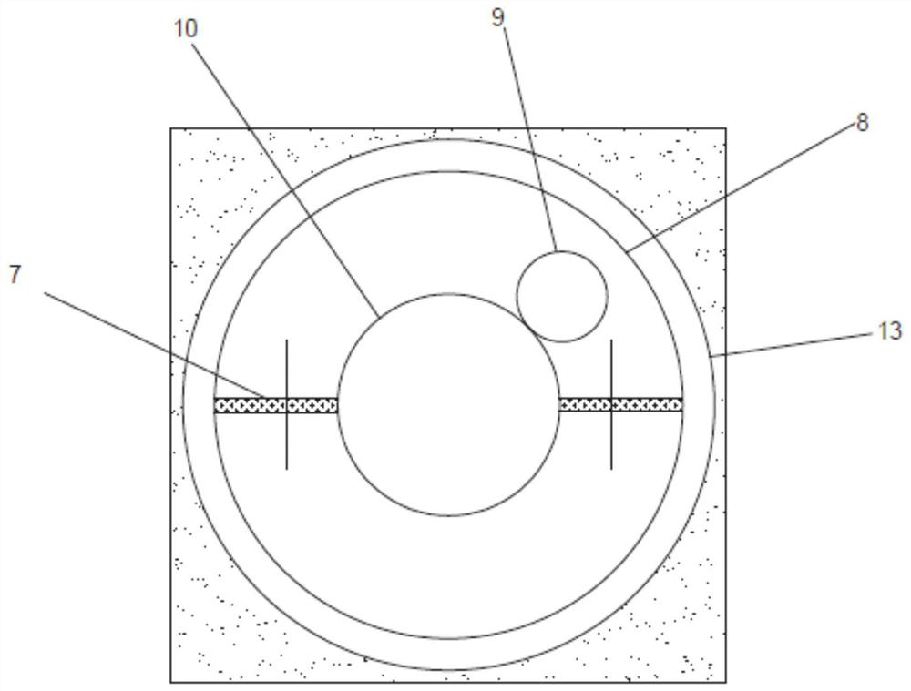
[0047] Casing, the diameter of which is smaller than the diameter of the borehole;

[0048] Grouting pipe, the bottom end of the grouting pipe is sharp, the grouting pipe is arranged on the inner side of the casing, and is movably connected with the casing so that the grouting pipe can move relative to the casing, the grouting pipe is provided with a grouting outlet, The sealing plug is sleeved in the circumferential direction of the grouting pipe, and the sealing plug is set close to the grout outlet;

[0049]Pipeline, the pipeline is set in the casing, and is set on the side of the grouting pipe, and one end of the pipeline is connected to the sealing plug;

[0050] After the casing moves relative to the grouting pipe, the part of the plug can protrude from the end of the casing, and gas or liquid can be filled or pumped into th...

Embodiment 2

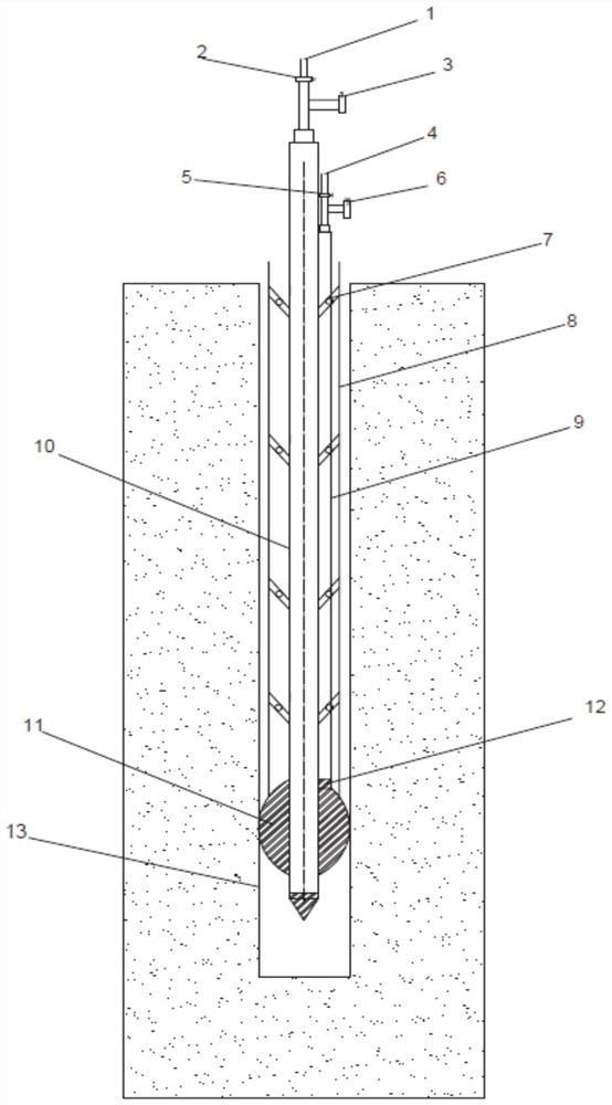
[0071] The differences between this embodiment and Embodiment 1 are:

[0072] A device for retreating grouting also includes a bracket that can be arranged at the end of the borehole and placed on the ground. The bracket is detachably connected to the casing, and the casing is fixed by the bracket so that the position of the casing remains unchanged, thereby relatively Move the grout pipe and piping around the casing.

[0073] A through hole is set in the center of the bracket, the sleeve is set through the through hole, bolts are respectively set on both sides of the bracket, and the bolt and the sleeve are detachably connected;

[0074] Alternatively, a flange is provided on the outside of one end of the casing, and the flange is detachably connected to the bracket;

[0075] Alternatively, one end of the casing is provided with a convex portion in the circumferential direction, the top of the convex portion is connected to the casing, and there is a set distance between the...


PUM


Abstract

The invention discloses a device for retreating grouting and a method for using it, which solves the problem in the prior art that the hole is prone to collapse and bury the grouting pipe, and solves the problem of hole wall collapse caused by plugging and expansion. , economical and practical, the beneficial effect of convenient operation, the specific scheme is as follows: a device for retreating grouting, including a casing, the diameter of the casing is smaller than the diameter of the borehole; the grouting pipe, the grouting pipe is arranged on the casing The inner side is movably connected with the casing so that the grouting pipe can move relative to the casing. The grouting pipe is provided with a grout outlet, and the sealing plug is sleeved in the circumferential direction of the grouting pipe, and the sealing plug is arranged close to the grouting outlet; The pipeline is arranged in the casing and on the side of the grouting pipe, and one end of the pipeline is connected with the sealing plug.

Description

technical field [0001] The invention relates to the field of grouting, in particular to a device and method for retreating grouting. Background technique [0002] The statements in this section merely provide background information related to the present invention and do not necessarily constitute prior art. [0003] Grouting is an effective method to strengthen weak ground, and has achieved remarkable results. Backward grouting is a commonly used method of grouting. In the past, most of the grouting pipes were sealed at the bottom to block the gap between the grouting pipe and the hole wall to increase the grouting pressure. [0004] However, the inventor found that the disadvantages of this retreating grouting device are: if the plugging pressure is high, the plugging will squeeze the surrounding soil, causing the soil on the hole wall to collapse, and the grouting pipe is buried in the hole ; If the plugging pressure is reduced to make the plugging pressure small, the g...

Claims


Application Information

Patent Timeline
Patent Type & Authority Patents(China)
IPC IPC(8): E02D3/12E02D15/00
CPCE02D3/12E02D15/00
Inventor 王洪波董粮林汤春阳刘泉维郑世杰张连震刘林胜
Owner SHANDONG UNIV OF SCI & TECH
Why Eureka
Try Eureka