Method and device for dragging out roller used for dragging steel rail below steel rail
A tractor and roller technology, which is applied to tracks, track laying, track maintenance, etc., can solve the problems of increasing labor costs, slow speed, affecting the progress of the track laying system, etc. Efficiency-enhancing effect
- Summary
- Abstract
- Description
- Claims
- Application Information
AI Technical Summary
Problems solved by technology
Method used
Image
Examples
Embodiment 1
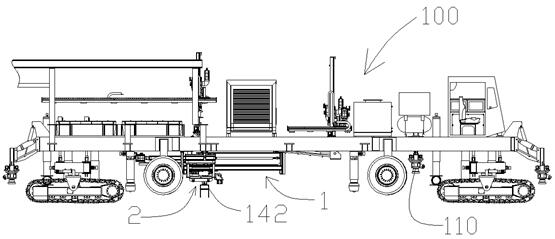
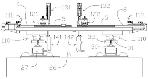
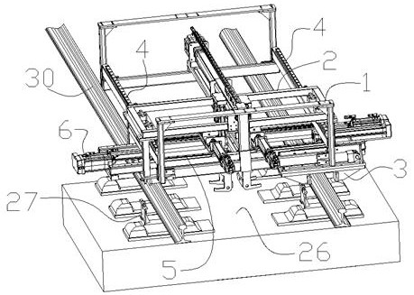
[0042] like figure 1 , 2 , shown in 3, a kind of device designed by the above-mentioned method that the roller 27 that is used for rail dragging under the rail 30 is dragged out, comprises the rail lift mechanism 110 that is arranged on the both sides of roller recovery vehicle 100, also includes the mechanism that is located at the recovery The active frame 2 on the car 100, the retrograde parking mechanism arranged between the active frame 2 and the recovery vehicle 100, the transverse drive mechanism arranged on the active frame 2, the longitudinal fine-tuning mechanism located on the transverse drive mechanism, and the longitudinal fine-adjustment mechanism The upper lifting mechanism and the hook part located at the lower end of the lifting mechanism. The rail lifting and sliding mechanism 110 arranged on both sides of the drum recovery vehicle 100 has two horizontally arranged pulleys 32, which are respectively added between the rail head 31 and the rail bottom on both ...
Embodiment 2
[0064] like Figure 10 As shown, a device for pulling out the roller 27 used for dragging the rail under the rail 30 is different from Embodiment 1 in that: the hook component includes a hook frame 33, an electromagnet that is arranged at the lower end of the hook frame 33 Suction cup 34, electromagnetic suction cup 34 is towards the left side or the right side of track bed 26 under the car belly. Correspondingly, the front and rear ends of the roller frame 28 are made of magnetic material such as iron, or a magnetic plate is directly installed. A strong electromagnetic coil is arranged in the electromagnetic chuck 34 to control the suction and release of the roller frame by cutting off the current. During application, the electromagnetic coil is energized, so that the electromagnetic chuck 34 is close to the roller frame 28, and after sucking the roller frame 28, the roller 27 is dragged to a limited position, and then the power is turned off and released. The advantage of ...
PUM
 Abstract
Description
Claims
Application Information
 - R&D Engineer
- R&D Manager
- IP Professional
- Industry Leading Data Capabilities
- Powerful AI technology
- Patent DNA Extraction
Browse by: Latest US Patents, China's latest patents, Technical Efficacy Thesaurus, Application Domain, Technology Topic, Popular Technical Reports.
© 2024 PatSnap. All rights reserved.Legal|Privacy policy|Modern Slavery Act Transparency Statement|Sitemap|About US| Contact US: help@patsnap.com


