Logic level conversion circuit from low voltage domain to high voltage domain

A logic level and conversion circuit technology, which is applied in the direction of reliability improvement modification, field effect transistor reliability improvement, delay compensation, etc., can solve the problems of inconsistent delay, large difference, increase, etc.

Active Publication Date: 2021-05-25
SG MICRO
View PDF6 Cites 0 Cited by
  • Summary
  • Abstract
  • Description
  • Claims
  • Application Information

AI Technical Summary

Problems solved by technology

Such a circuit structure uses many high-voltage devices, and the delay from input to output logic low to high / high to low is inconsistent and has a large difference, and increases with the increase of the voltage difference from the high voltage domain to the low voltage domain, it is difficult to guarantee Timely and effective logic signal transmission

Method used


Image

  • Logic level conversion circuit from low voltage domain to high voltage domain
  • Logic level conversion circuit from low voltage domain to high voltage domain

Examples


Embodiment Construction

[0015] Below with the accompanying drawings ( Figure 1-Figure 2 ) to illustrate the present invention.

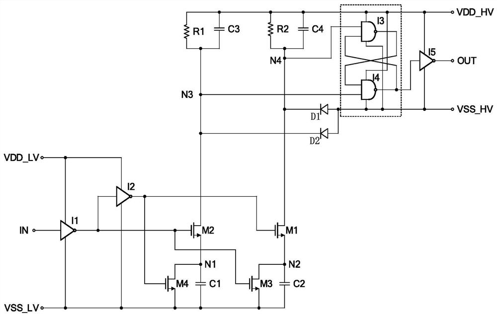
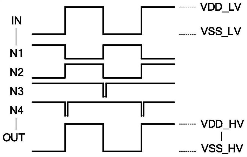
[0016] figure 1 It is a structural schematic diagram of a logic level conversion circuit from a low-voltage domain to a high-voltage domain for implementing the present invention. figure 2 yes figure 1 Schematic diagram of the timing of each node. like Figure 1 to Figure 2 As shown, a logic level conversion circuit from a low-voltage domain to a high-pressure domain includes an input inverter I1 and an output inverter I5, and the input terminal of the input inverter I1 is connected to a low-voltage domain logic input signal Terminal IN, the power contact of the input inverter I1 is connected to the low-voltage domain power supply voltage terminal VDD_LV, the ground point of the input inverter I1 is connected to the low-voltage domain ground terminal VSS_LV, and the output of the input inverter I1 One of the terminals is connected to the gate of the second NMOS trans...


PUM


Abstract

A logic level conversion circuit from a low-voltage domain to a high-voltage domain is characterized in that a combination of an RS latch and an RC parallel circuit is additionally arranged at a high-voltage domain logic output signal end, so that the logic low-to-high/high-to-low delay from low-voltage domain input to high-voltage domain output is basically consistent, and the logic low-to-high/high-to-low delay does not change along with the voltage difference change from the high-voltage domain to the low-voltage domain; therefore, timely and effective logic signal transmission between the low-voltage domain and the high-voltage domain can be ensured.

Description

technical field [0001] The invention relates to logic level conversion technology, in particular to a logic level conversion circuit from a low-voltage domain to a high-voltage domain. By adding a combination of an RS latch and an RC parallel circuit at the logic output signal end of the high-voltage domain, it can make the low-voltage domain The delay from input to high pressure domain and output logic low to high / high to low is basically the same, and does not change with the pressure difference from the high pressure domain to the low pressure domain, thus helping to ensure timely and effective logic signal transmission between the low pressure domain and the high pressure domain. Background technique [0002] The logic level conversion from the low-voltage domain to the high-voltage domain in the prior art includes an inverter at the input end of the low-voltage domain and an inverter at the output end of the high-voltage domain, and a MOS transistor circuit is used betwe...

Claims


Application Information

Patent Timeline
Patent Type & Authority Applications(China)
IPC IPC(8): H03K19/003
CPCH03K19/00323H03K19/00315
Inventor 宫志超
Owner SG MICRO
Why Eureka
Try Eureka